Just looking for replacements for VR401 / VR402 but can't find a similar size, thinking of fitting the on the under side of the PCB?
Thanks again
David
Thanks again
David
I have set the speaker outputs to 0mV on both channels VR401/402 replaced. I then proceeded to the idling current, removed the two shorts on R461/462 and attached my Fluke to R461 1ohm and was reading a little high at 36mV. I removed RX1 and added a 500ohm variable resistor adjusted to 27mV and fitted a 390ohm fixed resistor for RX1, retested to ensure I had 27mV. I then moved to RX2 again a little hight again, added the variable resistor to RX2 but could not get it to adjust like RX1, then the DBT illuminated when adjusting the variable resistor...I turned off and looked for damage but nothing visible but found that Q414 had blown and R462 1ohm.
I replace both and attached to the DBT tester one quick flash, short gone?. I connected the fluke again to the replaced R462 1 ohm, powered on but this time the mV reading started at 6mV and started to clim to 65mV at this point I power off.
Do the 2N3055 and MJ2955 have to be matched pairs as the fault is on the side I replaced them, would the volume control have any effect on adjusting RX2 or have I done something wrong when setting the idling current? (Photo attached of the T03's fitted).
That sounds like a classic case of thermal runaway. Did you fit those 0.47 ohm emitter resistors I mentioned earlier?powered on but this time the mV reading started at 6mV and started to clim to 65mV at this point I power off.
No I'm still waiting for them to arrive so attempted to set the Idling current, did not realise thermal runaway would be an issue?
Why did the thermal runaway only affect the side I repaired and not the other side as I had no problems setting the 27mV?
Why did the thermal runaway only affect the side I repaired and not the other side as I had no problems setting the 27mV?
Last edited:
No I'm still waiting for them to arrive so attempted to set the Idling current, did not realise thermal runaway would be an issue?
One of the first amps I ever built suffered from this. It was a design in Practical Wireless and the bias current was on a knife edge and it literally could just 'run away'. Quasi complementary stage using two TIP3055's.
Why did the thermal runaway only affect the side I repaired and not the other side as I had no problems setting the 27mV?
Hard to say at a distance. Are both channels using identical semiconductors for driver and outputs? Even small differences in bias current and differences in chassis layout with respect to getting the heat away from the transistors make big differences in something like this. Adding emitter resistors should take all that away.
Yes I did check all on the list but no R649 but had already replaced R449 & R450, just checked them again and R460 reads 56 ohm the lettering hard to read its located between Q412 and C436 and I thinks it should 560 ohm?Did you chech the 33ohm at the base of the driver, that's critical and I did list it to check.
you should have +/- voltages either side of this resistor (R460)
what value resistors did you end up putting in RX1/2?
so what value on the good channel
so what value on the bad channel
they should both be around about the same, more or less give or take 50 ohms
what value resistors did you end up putting in RX1/2?
so what value on the good channel
so what value on the bad channel
they should both be around about the same, more or less give or take 50 ohms
Thing are going from good the bad, fitted new a 560 ohm for R460 and repaired a crack in the trace on C436. Good RX1 has a new 390 ohm and RX2 bad has 446 ohm (original resistor). However, R448 100 ohm is now burning (magic smoke) when I power on, tested Q410, Q412,Q406,Q404 & Q402 all tested OK?
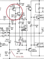
I have replaced R448 100ohm's Q408/669A,Q412/BD139 & Q414/BD140 to match the working side, all parts remove tested Ok and no Magic smoke on power up!check these sections where circled
Replace the 100ohm and quickly check what voltage you have where ive indicated R458
check the voltages either side of C454
The voltages have been measured from chassis ground with the short at R461/462 removed, Voltage at R454 41v and at the junction of R456/R458 47v, and not the -21 to 25v indicated in your latest reply, both are very high compared to the working side?
I did test the idling current again at RX1 = 31mV and RX2 jumping between 1-2mV, at this point I stopped and did not attempt to set the mV for either side due to the high voltages?
and at the junction of R456/R458 47v
What is the voltage on the other end of R458? First thought is the negative rail is missing.
- Home
- Amplifiers
- Solid State
- NAD 3130 PCB Track layout