After a long time that I stashed some 2sk182es sits I decided to use them. So the last year I did a small prototype pcb following Pa`s Got Vfets? schematic and it looked like this

The sound was nice so I decided to draw a pcb.


The Sit sounds nice and measures nice too


So after a while of playing with the Sit I replaced it with a power jfet(Sjep120r100) and the irfp150 mosfet in the ccs was replaced by 2sk3497.
The sound was very similar but I liked it a bit more. It is measuring a bit better too.


And the jfet/mos combo played music for quite a while. At the end of the last year I found some puck mosfets that I had unused from another project and wanted to try them.
So I checked all of them for vgs @3A and heated to 55C.

Initially I replaced the power jfet on one pcb with a puck mosfet and did some measurements. It was nothing spectacular but I decided to draw a new pcb to use them. So I drew the pcb but unfortunately didn`t have the funds until now to proceed with the components order.
So now that the sun went up and the components jumped from all over the places 🙂 it was the time to build the puck version.
This version doesn`t use Pa`s optocoupler to regulate the bias instead it uses lhquam idea of using a bjt comparator.
So here is what I come up with:


All good until here and even better from now on.
I had the pleasant surprise to find out that these pucks are doing better than the sjep120r100 and 2sk3497 combo. Beside that these(sjep120r100 and 2sk3497) are very hard to source and are very expensive too.
Here some measurements


I call it sePP because there is an onboard trimmer that lets you adjust how you want the amp to work, se or pp.
If there is somebody interested about this I still have some pucks to sell together with the pcbs.
The actual pcb can be used with sits too, I will test this someday...when time comes.
I drew also a smaller pcb that doesn`t host the upper mosfet and the output coupling cap being specially designed(for a friend) to be used with sits. Unfortunately I didn`t order this one and I am not sure I will ever order it.

A big thanks to Pa, ZM and lhquam.
The sound was nice so I decided to draw a pcb.
The Sit sounds nice and measures nice too
So after a while of playing with the Sit I replaced it with a power jfet(Sjep120r100) and the irfp150 mosfet in the ccs was replaced by 2sk3497.
The sound was very similar but I liked it a bit more. It is measuring a bit better too.
And the jfet/mos combo played music for quite a while. At the end of the last year I found some puck mosfets that I had unused from another project and wanted to try them.
So I checked all of them for vgs @3A and heated to 55C.
Initially I replaced the power jfet on one pcb with a puck mosfet and did some measurements. It was nothing spectacular but I decided to draw a new pcb to use them. So I drew the pcb but unfortunately didn`t have the funds until now to proceed with the components order.
So now that the sun went up and the components jumped from all over the places 🙂 it was the time to build the puck version.
This version doesn`t use Pa`s optocoupler to regulate the bias instead it uses lhquam idea of using a bjt comparator.
So here is what I come up with:
All good until here and even better from now on.
I had the pleasant surprise to find out that these pucks are doing better than the sjep120r100 and 2sk3497 combo. Beside that these(sjep120r100 and 2sk3497) are very hard to source and are very expensive too.
Here some measurements
I call it sePP because there is an onboard trimmer that lets you adjust how you want the amp to work, se or pp.
If there is somebody interested about this I still have some pucks to sell together with the pcbs.
The actual pcb can be used with sits too, I will test this someday...when time comes.
I drew also a smaller pcb that doesn`t host the upper mosfet and the output coupling cap being specially designed(for a friend) to be used with sits. Unfortunately I didn`t order this one and I am not sure I will ever order it.
A big thanks to Pa, ZM and lhquam.
Attachments

You helped with implementing the modulation trimmer, the sePP one 🙂
On some of the designs it was useful.
On some of the designs it was useful.
This looks very interesting. I like to see use of commonly available parts, and parts that will likely remain available for a while.
I recently finished the Aleph J SemiSouth, but with without using the rare SemiSouth components. The single-ended operation of the Aleph J has been wonderful to listen to, and also has remarkable rejection of power supply ripple.
The SMD parts are being used well here. They are going to be less expensive than leaded parts, and available for more types of devices in the future.
It looks like each channel dissipates about 200W? So good sized heatsinks will be necessary.
I would like to sign up for a pair of boards & pucks.

ZM, is there a measurement of transconductance or Id v Vgs in the area of interest, say between 1-10A? Maybe on diyaudio? Thanks!What I've done now?
so, tnx to Pa, lhquam and wakoo puck's xconductance
Forgot about the schematic..

For now I power them up with 50Vdc and I keep the bias around 2amps so 100w of heat.
I have some STE250NS10 that I will try but these are already obsolete
For now I power them up with 50Vdc and I keep the bias around 2amps so 100w of heat.
not sure what to tell about the IXFN280N085I like to see use of commonly available parts, and parts that will likely remain available for a while
I have some STE250NS10 that I will try but these are already obsolete
It is definitely good to see the schematic. It answers a few important questions.
A single rail power supply is easier to manage, and I already have a chassis or two that will handle that amount of heat.
The IXFN280N085 is certainly a capable looking part. Like many, it is available to order rather than being in immediate stock. Another part to consider would be the IXFN140N20P. This one has been used in similar “hockey puck” amp designs, and I happen to have a small number already in hand.
Always good to see new development in progress.
ZM, is there a measurement of transconductance or Id v Vgs in the area of interest, say between 1-10A? Maybe on diyaudio? Thanks!
yeah, yah and naah
I can reveal just Unit for puck's xconductance, it is not Siemens ....... it is Whoa, Blue Car full of Siemenses!!
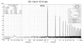
Yesterday I replaced the IXFN280N085 mosfets with STE250NS10.
With the last one I get a bit more 2nd hd and less 3rd hd this because of the higher capacitance and higher transconductance.
At low power the thd is a bit worse if you want to look at it that way but at higher power levels it looks better when driving 4ohm loads. Into 8ohm it performs a bit worse.
When using 8r loads the modulation doesn`t change things very much as it does for 4r.
So depending on your speakers impedance and also on what you like you can set it as a single ended or as a push pull. When set as single ended it gives a bit worse performance but it gives negative 2nd.
The graphs that end with pp mean that the amp was set as push pull and the graphs that end with se mean that the amp was set as single ended.
The tests that I had published for the earlier versions of this amp had it configured as push pull.
As for the sound...it sound nice configured as se as well as pp though I don`t know why but I seem to like it more configured as se. As pp the soundstage seems more focused and as se seems wider.
I have one small question..
If one has 2 amplifiers and both use same topology(schematic).
One amp has lower thd @1khz and lower imd(19+20khz test) and the other has lower thd @10khz.
Which of the two would you consider better?
If one has 2 amplifiers and both use same topology(schematic).
One amp has lower thd @1khz and lower imd(19+20khz test) and the other has lower thd @10khz.
Which of the two would you consider better?
For my lousy ears the lower imd sounds better…it’s difficult to detect the difference in thd @10khz
Agree with ears. Thd at 10 kHz is basically just 2nd harmonic that falls at 20 kHz. The main thing 10 kHz thd compared to 1 kHz thd will tell you is how it will do on large transients.
I have found something interesting today.
The last week I connected the puck sepp to a 50v ps and dialed the bias to 2.2a bias. The heatsink that I use is not capable of handling this kind of heat but I said it will be enough to do some thd testing.
Kept everything on for 10-15mins. The heatsink was hot, I suspect 80c by the touch🙂 maybe more..
I turned the amp off for a minute and then I turned it back on. At startup the bias goes to more than 4a until the bias circuit takes control.
So as soon as the bias reached 4a(it was biased at 2.2a) I heard PUFF PUFF. Oh boy I said to myself something burned out. Checking on the power supply the bias was 0a and the supply wasn’t in cc protection.
I disconnected everything, unmounted the pcb from the pucks and then measured the big guys.
Well surprise.. I measured a few ohms between DS on both pucks. Hmm this was strange because the sense resistor didn’t blow up and it should had in this case.
So I left them on the floor and replaced them with another pair considering them dead and to be thrown away.
Today I wanted to throw them away but I my heart didn’t let me do it without measuring them again.
Surprise again. The short disappeared so I connected them back in the circuit which biases again to 2.2a and most important they sing again.
Did anyone experienced something like this and have any idea what could have happened when I heard the PUFFs coming from the pucks?
I can't remember having that case - of overcurrent then Dodo than alive
in fact, even if I probably had during prototyping some mishap, I can't remember ......... and all pucks I have are more than alive
I'll try tonight to grasp biasing scheme you have ( partial schematics drawn with funny symbols), so no momentary aha! process
in fact, even if I probably had during prototyping some mishap, I can't remember ......... and all pucks I have are more than alive
I'll try tonight to grasp biasing scheme you have ( partial schematics drawn with funny symbols), so no momentary aha! process
I have simulated the circuit and I noticed the same behavior. It`s due to R3 being too big. If I power on with 50V, I get 10% increase in the bias.
If I power on with 19V I get close to 2x the bias.
If I start my power supplies setup for 50V they go into cc protection. So I have to start them at 20V and then ramp up the voltage.
Now I got it from where the 2x bias.
If I power on with 19V I get close to 2x the bias.
If I start my power supplies setup for 50V they go into cc protection. So I have to start them at 20V and then ramp up the voltage.
Now I got it from where the 2x bias.
- Home
- Amplifiers
- Pass Labs
- Puck sePP (MUFF) Follower