There was no hum after 1 minute of booting before the electronic filter was added, and this situation disappeared after the addition of electron filtering.
PS:Can I assume that the voltage at the key points on my amp is slightly lower than what you call, but is it normal?
PS:Can I assume that the voltage at the key points on my amp is slightly lower than what you call, but is it normal?
The key voltages are that the output DC offset should be almost zero, there should be approximately 22 millivolts across each 0.22 ohm resistor and there should be approximately 600mv across the 100 ohm in the current source.
These are typical voltages. Some are supply dependent.

These are typical voltages. Some are supply dependent.

I'm in the preliminary stages myself. This one is the next cab off the rank once I get my Rod Elliot P3A dialed in.
I have all the parts but I am yet to order pcbs.
I am still working on my PSU.

Standard sort of cap bank arrangement with dual rectifiers, C,RC snubber network.
With what is basically a mono Rod Elliot P33A speaker protection onboard the PSU.
I am planing to make some mono blocks in some home build chassis.
Before I order the pcbs I need to check everything is going to fit like I want with my heatsinks, power transformers, output relay arrangement etc.
Should be a fun build.
I have all the parts but I am yet to order pcbs.
I am still working on my PSU.
Standard sort of cap bank arrangement with dual rectifiers, C,RC snubber network.
With what is basically a mono Rod Elliot P33A speaker protection onboard the PSU.
I am planing to make some mono blocks in some home build chassis.
Before I order the pcbs I need to check everything is going to fit like I want with my heatsinks, power transformers, output relay arrangement etc.
Should be a fun build.
I have just placed an order for some PCBs.
Anybody in NZ or Aus is welcome to grab the extra pair for cost + shipping.
Anybody in NZ or Aus is welcome to grab the extra pair for cost + shipping.
me too... 😉
renesas LATEFET´s are on stock at home.
but..
i thought i understand a bit of the behavior of an amp.
so my questions:
for double output amp is "just" one single BJT 2N5551 as T6 (or 2N5401 as T7) good to give 2 gates enough current into max power setting?
and which hfe setting is good here?
for DC opamp AD822 better then TL071?
chris
Attachments
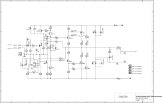
One single pair are easily enough. The gate current is very low indeed and is absolutely swamped by the driver current (which itself is low in any case).for double output amp is "just" one single BJT 2N5551 as T6 (or 2N5401 as T7) good to give 2 gates enough current into max power setting?
Higher hFE would normally give a higher open loop gain for an amp and so give lower distortion when the feedback loop is closed but I think any differences will be pretty minimal here. T1 and T4 in your diagram would benefit most from having high hFE.and which hfe setting is good here?
It seems to tick all right boxes and (in simulation) is one of the few opamps that will work correctly with the single negative rail while having the supply pin and non inverting input tied together. It would need proving in a real a build though.for DC opamp AD822 better then TL071?
Hi Mooly,
it's been only ~5 years since my last attempt at your amp, and here I am at it again 🙄. Sometimes life gets in the way...
Anyhow. I've been tinkering a bit more with the simulation files and noticed something odd in the frequency domain. As far as I can tell, this "issue" (if I may call it so) hasn't come up yet in this thread. For reference, I have used your simulation files from Post #312, specifically the one for the ripple simulation, since that one is all set up for an AC simulation already.
If you run this file in AC and look at the resulting frequency response at the output of the amp, you will see a peak of an additional +14dB at around 6Hz. This gain peak is not only seen in AC, but in the time domain as well (red trace):


As a first-attempt-fix I have reduced the value of C6 by an order of magnitude, see the yellow traces. On power-on, the output will now only swing upwards once (and not as high up as before) and settle much faster. The input signal, starting at 3 seconds, is set to 100mV at 6Hz for both cases, and yet the output level is wildly different.
This should not be an audible problem, and that is probably why nobody noticed it before, I'd guess. But it raised a red flag for me when I was thinking about using a record player as the source. Think about a warped record, or a badly damped tone arm resonance in that sub-sonic range. That would lead to some severe cone excursion of the speakers!
What do you think; anything wrong with reducing C6 from 470uF to 47uF and call it a day?
it's been only ~5 years since my last attempt at your amp, and here I am at it again 🙄. Sometimes life gets in the way...
Anyhow. I've been tinkering a bit more with the simulation files and noticed something odd in the frequency domain. As far as I can tell, this "issue" (if I may call it so) hasn't come up yet in this thread. For reference, I have used your simulation files from Post #312, specifically the one for the ripple simulation, since that one is all set up for an AC simulation already.
If you run this file in AC and look at the resulting frequency response at the output of the amp, you will see a peak of an additional +14dB at around 6Hz. This gain peak is not only seen in AC, but in the time domain as well (red trace):
As a first-attempt-fix I have reduced the value of C6 by an order of magnitude, see the yellow traces. On power-on, the output will now only swing upwards once (and not as high up as before) and settle much faster. The input signal, starting at 3 seconds, is set to 100mV at 6Hz for both cases, and yet the output level is wildly different.
This should not be an audible problem, and that is probably why nobody noticed it before, I'd guess. But it raised a red flag for me when I was thinking about using a record player as the source. Think about a warped record, or a badly damped tone arm resonance in that sub-sonic range. That would lead to some severe cone excursion of the speakers!
What do you think; anything wrong with reducing C6 from 470uF to 47uF and call it a day?
What do you think; anything wrong with reducing C6 from 470uF to 47uF and call it a day?
It looks very feasible. If you cut the opamp from the sim and replace it with a voltage source of exactly the same voltage value as the DC output from the opamp you can look at the response without the servo having an effect. Back when this was all put together I didn't have the benefits of simulation.
Without the servo the -3db point with 470uF is <1Hz and with 47uF is around 7Hz.
This is with 47uF and a 0.15u for the servo. That would increase the settling time a little of course.
Purely in terms of wattage 0.25 watt covers everything apart from the 0.22 ohms and the 10 ohm Zobel and coil damping resistor but I would suggest 0.5 or 0.6 metal film and particularly for high value resistors that have significant voltage across them such as the resistor feeding the opamp Zener supply and the 100k in the constant current source. The 10 ohm's should be at least 2 watt (which is fine for anything other than lab testing at sustained high output voltage at very high frequency). The 0.22 ohms are 3 watt such as the Welwyn W21 0R22 JII've had some pcbs made for this, but am wondering what wattage the resistors should be?
I'm noticed the same thing for the AC response. I replaced the servo with a voltage source as Mooly suggested and found that the response flattened. This leads me to believe the servo is responsible for the spike (at least in simulations). I've found that increasing the servo cap from 0.1u to 4.7u to 10u flattens the low frequency response. I don't claim to understand why though. By the math, the 0.1u should be fine. So there must be something else interacting with this that we aren't accounting for.
.. or it's a simulation issue. You'd have to build and test to see if its a real issue or a simulation artifact.
.. or it's a simulation issue. You'd have to build and test to see if its a real issue or a simulation artifact.
- Home
- Amplifiers
- Solid State
- My MOSFET amplifier designed for music