Hello guys,
I've got an amplifier with 2 Fets IRFU4615 driven by IRS20124S.
Problems:
1) Fets get hot after less than 1 minute, with no load.
2) I have 0.7V more on the +OUT than on the -OUT (the -OUT being connected directly to the middle of 2 supply voltage capacitors = 130VDC, while the +OUT is coming from the Fets). For example: If I have 63V on the -OUT, then, I will get 63.7V on the +OUT which comes from the Fets through a coil.
The amplifier seems to work fine, sound is OK, before the Fets get hot.
What should be tested? What could be wrong?
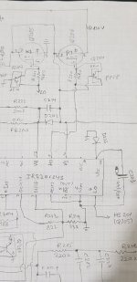
I will attach a simple scheme, and scope diagrams of some pins.
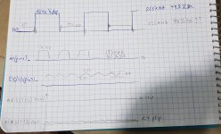
What should the signal look like on the gates of the Fets, if no load/audio signal present?
Thanks you all....
I've got an amplifier with 2 Fets IRFU4615 driven by IRS20124S.
Problems:
1) Fets get hot after less than 1 minute, with no load.
2) I have 0.7V more on the +OUT than on the -OUT (the -OUT being connected directly to the middle of 2 supply voltage capacitors = 130VDC, while the +OUT is coming from the Fets). For example: If I have 63V on the -OUT, then, I will get 63.7V on the +OUT which comes from the Fets through a coil.
The amplifier seems to work fine, sound is OK, before the Fets get hot.
What should be tested? What could be wrong?
I will attach a simple scheme, and scope diagrams of some pins.
What should the signal look like on the gates of the Fets, if no load/audio signal present?
Thanks you all....
Could be a dead time issue, both mosfet open fraction of a second, gate drivers a second problem maybe
Try ditching the transistors across the gate resistors and put in some fast schotky diodes pointed towards the irs and then report back,Other issues might be improper deadtime, frequency too fast(altough your 255k is fine),or output inductor saturation,but this seems to be the easiest thing to tackle at first,

But I have the ZFW over there(Q203, Q204). Do you mean to add on parallel to R220, R221, with the ZFW connected?
Thanks
Thanks
Definitely put Schottky diodes pointing back to the driver like PetruV suggested. Also, the gate resistors are a little higher value than what I use. I don't know what's recommended with the IRS20124, but I'm using 4.7 ohm with my IR2184. Could make the transitions a bit faster. The best thing to do is to connect both gates to an oscilloscope. The dead time will be easy to see and measure.
Here's what the gate voltages look like on my amplifier. The yellow curve is the transistor connected to the positive rail and the blue is the one connected to the negative rail. You can clearly see the dead time when the positive MOSFET shuts off and the negative one comes on. The curve looks a bit strange when the top one turns on. This is because the signal is referenced to the source and not ground. So the point where the transistor turns on is at the extra little step at the top of the yellow curve. Each division is 800ns and it looks like the dead time is about half a division, which matches up with the spec that says 500ns. Yours should be in that range as well. Definitely not shorter.

Here's what the gate voltages look like on my amplifier. The yellow curve is the transistor connected to the positive rail and the blue is the one connected to the negative rail. You can clearly see the dead time when the positive MOSFET shuts off and the negative one comes on. The curve looks a bit strange when the top one turns on. This is because the signal is referenced to the source and not ground. So the point where the transistor turns on is at the extra little step at the top of the yellow curve. Each division is 800ns and it looks like the dead time is about half a division, which matches up with the spec that says 500ns. Yours should be in that range as well. Definitely not shorter.
Closeup with cursors turned on. Looks like my dead time is only 380ns, but as you can see, it's enough. The gate of the positive side is completely discharged about 200ns before the negative side is turned on.

I think 100-150ns is pretty common, larger values can increase losses from the body diode conducting,Depends on the switching frequency and mosfets chosen,ones that have larger dies and built on older technology require more, while new small ones require less,yet another parameter you have to tune in your amplifier,as if there weren't enough already
I've tried what you suggested here. I couldn't see much difference after conneting fast switching diodes in paraller to R220, R221. I still have a very low deadtime, around 50ns. The amp was built as shown in my scheme, and it's not a new amp that I am trying to design. So, something else must be faulty, I suppose, as it worked before. The Irs20124s has its own deadtime generator as explained in the datasheet. They also do not mention high deadtime.
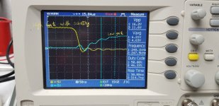
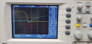
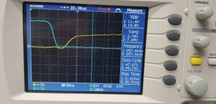
Please see attached pix, before and after diodes being connected.
Yellow signal= at gate of the high out / 130Vptp
Blue signal= at gate of the low out/ 10Vptp
50ns time division.
In the datasheet, the VCC of the driver should be connected to 20V. But the manufacturer of the amp, designed it with 10V Vcc supply.
The mosfets still heat up quickly.
Should a 0.7v output offset be an issue here?
Attachments

Nope. Although your DC offset is a bit high and you eventually want to trim it out, it won’t make your MOSFETs that hot. I had 2.5V offset before everything was dialed in and the MOSFETs were barely body temperature.
Lower FET is turning on too slowly? This will increase heat. Try 4R7 gate resistor like suggested earlier.
The MOSFETs may have failed partially; the gate capacitive barrier may have become slightly conductive.... this will manifest in oscillations. Check with an oscilloscope... short the inputs. The oscillations will shoot through the gate resistor towards the driver IC... which will eventually take the driver IC out.
... same problem with a 4ohm load (and shorted inputs)??
What is the impedance of your speakers?
... same problem with a 4ohm load (and shorted inputs)??
What is the impedance of your speakers?
The MOSFETs may have failed partially; the gate capacitive barrier may have become slightly conductive.... this will manifest in oscillations. Check with an oscilloscope... short the inputs. The oscillations will shoot through the gate resistor towards the driver IC... which will eventually take the driver IC out.
... same problem with a 4ohm load (and shorted inputs)??
What is the impedance of your speakers?
Do you thihk the mosfets are broken already? What do you mean by shorting the inputs?Lower FET is turning on too slowly? This will increase heat. Try 4R7 gate resistor like suggested earlier.
There is one 3.6 Ohm speaker and 3.3 Ohm Tweeter. From the amp 2 wires go out for the crossover card and this one feeds the speaker unit with 4 wires.
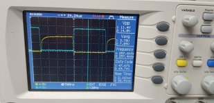
I've tried 5R1 gate resistor for each gate. Not much difference. The only difference I could see is the smooth transitions.Lower FET is turning on too slowly? This will increase heat. Try 4R7 gate resistor like suggested earlier.
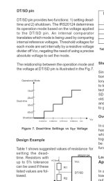
Have a look at the previous pix for comparison, The deadtime didn't change I think. So I am still stuck with the same heating. Maybe I should try to connect a higher R1 for the IRS deadtime generator? As seen in the datasheet above.
Attachments

My deadtime doesn't reach even 100ns. So critical also on the transition from Low to High rail. Please see also what I've reported earlier.I think 100-150ns is pretty common, larger values can increase losses from the body diode conducting,Depends on the switching frequency and mosfets chosen,ones that have larger dies and built on older technology require more, while new small ones require less,yet another parameter you have to tune in your amplifier,as if there weren't enough already
When I tried the 5R1, I put back the ZFW instead of the switching diodes.
As I reported, the signals got more smooth, but the heat is still present!!!
- Home
- Amplifiers
- Class D
- MosFET getting hot in amp - with no load