Variant 4 (attachment), it’s difficult to comment and I probably won’t, because I kind of know the sound of such a design, but with such an output stage and the parameters that I saw, it’s difficult to comment on the final sound.
Miller’s correction is not accidental here; if it were possible to apply a progressive correction, I would have installed it, but no, it is Miller’s correction that is relevant here.
Peculiarities:
* stable initial current with little dependence on heating inside the amplifier housing.
*the level of distortion does not depend on the output power level and at a frequency of 1 kHz is 0.001%, at a frequency of 20 kHz - 0.01%.
Attachments

Explain Q12/13 , I might simulate this one - different....Peculiarities:
* stable initial current with little dependence on heating inside the amplifier housing.
*the level of distortion does not depend on the output power level and at a frequency of 1 kHz is 0.001%, at a frequency of 20 kHz - 0.01%.
Also , IRFP's I use at 50-60 volts , the Sub amps I used them in can do >150W. My reason for interest is that I want a 2 device sub amp
that can out power a single BJT pair. Yes , why such low rails ?
Yes, you are right, such distortions at higher frequencies are obtained due to the current control circuit, which is located in the voltage amplifier line to control the initial current..04% 20K - for audiophiles ?? That is where I look for what is "broken" (or non- linear) in the design. A good design stays <30 PPM right up to clip
at all audio freqs.
I’ll try to reduce its influence by using a Wilson current mirror in the voltage amplifier, this will improve the gain at high frequencies and accordingly reduce distortion by an additional gain.
such a driver eliminates the location of the BIAS multiplier in the voltage amplifier circuit, this improves the matching of the voltage amplifier and the output power stage.Explain Q12/13 ,
How?I might simulate this one - different....
You can call it as you like and confuse forum participants. It is not Moller correction it is Miller compensation 😉thank you, I call this a “broken cascode”; the topology is clearer this way, and the adjective does not stop this cascade from being a cascode.
Try using Google-translator so as not to get confused and the forum will sort it out without your participation.It is not Moller correction it is Miller compensation 😉
what's the point of compensation if there is a correction? 😉
Last edited:
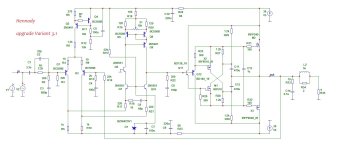
here is the upgrade that I mentioned, here the supply voltage is already below +/-36 volts and distortion at 1 kHz is less than 0.001% at a frequency of 20 kHz 0.007% - the initial current of the output mosfets is 200 mA, for thermal stabilization all transistors of the output stage are placed on one radiatorThat is where I look for what is "broken" (or non- linear) in the design.
Attachments
Sorry, not Miller correction but Miller compensation, it's in English noting to translate.
I hope I understood you correctly about compensation in the cascode, but I was talking about external correction.Sorry, not Miller correction but Miller compensation, it's in English noting to translate.
Google Translator sometimes has difficulty translating special concepts in audio technology.
I don't understand what you meen by external correction? Could you show what capacitor is for Miller correction on your schematic.
By the way I do not use Google-translator to write here. We need to use correct electronic terminology here to prevent confusion.
By the way I do not use Google-translator to write here. We need to use correct electronic terminology here to prevent confusion.
progressive correction does not imply Miller external correction.I don't understand what you meen by external correction? Could you show what capacitor is for Miller correction on your schematic.
for example, в схеме пост 21 Miller external correction - С11, but it is not present in the post 28 circuit, but it looks like it will need to be added to the Q9 transistor - a 4.7 pF capacitance between the collector and emitter.
Ok it's clear to me now, but it is called Miller (frequency) compensation not correction.
Gogle translation from Ukrainien is not good enough.
Gogle translation from Ukrainien is not good enough.
maybe that's what you call it.Ok it's clear to me now, but it is called Miller (frequency) compensation not correction.
We call this correctly - we compensate for Miller’s parasitic capacitance with a low-impedance load, and we correct the amplitude-frequency response with external Miller capacitance.)))
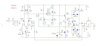
A version of the simplest amplifier using mosfets IRF240/9240 with normal parameters. A modified version of the very first version from the topic.
peculiarities:
peculiarities:
- progressive correction
- in the driver there are lateral transistors
- distortion thousandths
Attachments

Ah , wilson mirror !! that will do the job. looks like 3.1 is the folded/"broken" cascode , as well. Lower OLG , but very linear.here is the upgrade that I mentioned
LT spice , of course.How?
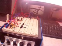
I even have the protoboard to build it in the real world , Built in LM317/337 ' will do +/- 25V. I have a +/- 50V if I really need it...
Attachments
Yes, but I don’t like how it works in this circuit, because... due to the appearance of local feedback through the Q5 transistor, it is necessary to further adjust the frequency properties of the Q9 transistor. Those. This option still needs further development.Ah , wilson mirror !!
It’s impressive; we had similar stations at our university.I even have the protoboard to build it in the real world , Built in LM317/337 ' will do +/- 25V. I have a +/- 50V if I really need it...
P.S. Ok, I'll try to redesign the modes for a supply voltage of +/-50 volts
Last edited:
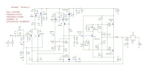
Look, I made an upgrade to 3.2 for the supply voltage +/-50 volts:looks like 3.1
peculiarities:
- use 8 ohm load (input power 115 watts)
- removed Wilson, made a current mirror with a cascade with a common Q9 base.
- distortion at 20 kHz decreased to 0.0089%
- in the output stage, for symmetry, the level shift was made on the same type IRF510 (M1 M2) for the positive and negative half-waves of the output stage control.
we get: no Wilson, no external Miller correction, all stages in linear mode.
Q11 and Q12 dissipate 0.8 watt(t) of heat each.
I think Variant 3.2 it turned out almost well.
Attachments
finalized version 3.3 possible for assembly.
I described all the modes:
* Q12Q13 will need small local radiators 15-20cm. sq.
*thermal stabilization is carried out due to the arrangement of transistors Q11Q14 on a common radiator with output power Mosfet transistors X2M3
*initial current of Mosfet transistors is set to 112mA
*if there is a need to adjust the initial current, select R27R28 in pairs with an equal rating
* The input stage transistors do not require additional cooling.
*установка нуля на выходе осуществляется триммером Х1,
*остальные параметры указаны на схеме
*for speaker systems with an impedance of 4 ohms, it is necessary to reduce the supply voltage to +/-36 volts
*gain = 20dB
Attachments

- Home
- Amplifiers
- Solid State
- Amplifier with output power transistors IRF240/9240