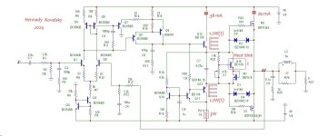
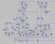
I am posting an amplifier circuit for working with IRF240/9240 as output transistors.
Amplifier Feature:
*original high-current driver for the output stage
*progressive correction
*high linearity of cascades
*insensitive output stage to complex load
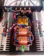
The attachment shows a simplified version of the circuit, which was assembled 2 years ago (the photo in the attachment shows its implementation)
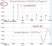
also, the model obtained a very small % of distortion, while other models showed data on par with the measured parameters.
*For Q11 nun a small plate for cooling
*Q12Q13 is best placed on the main radiator, because they need to dissipate 1.2 watts of heat each
*temperature stabilization - place Q14 on the radiator
*output transistors IRF240/9240 initial current 80mA - Bias trimmer X1
*There are no source resistors for the IRF240/9240 outputs to improve sound quality
*output power 100 watts into a 4 ohm load
*distortion 1kHz - 0.0006%, 20kHz - 0.0008%
*input voltage 1.5 volts RMS
*gain 20dB
*OpenLoop Gain 108dB
Amplifier Feature:
*original high-current driver for the output stage
*progressive correction
*high linearity of cascades
*insensitive output stage to complex load
The attachment shows a simplified version of the circuit, which was assembled 2 years ago (the photo in the attachment shows its implementation)
also, the model obtained a very small % of distortion, while other models showed data on par with the measured parameters.
*For Q11 nun a small plate for cooling
*Q12Q13 is best placed on the main radiator, because they need to dissipate 1.2 watts of heat each
*temperature stabilization - place Q14 on the radiator
*output transistors IRF240/9240 initial current 80mA - Bias trimmer X1
*There are no source resistors for the IRF240/9240 outputs to improve sound quality
*output power 100 watts into a 4 ohm load
*distortion 1kHz - 0.0006%, 20kHz - 0.0008%
*input voltage 1.5 volts RMS
*gain 20dB
*OpenLoop Gain 108dB
Attachments
Last edited:

=Q10,11,13 ?? (I think I know) VERY interesting circuit .... explain Q7,8,and 9 better. PS - though you said simple was not better ?*progressive correction
OS
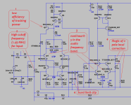
triple current generator for operation of the Q12 driver in class A with local stabilization of the operating point for controlling IRFs=Q10,11,13 ??
stabilizes the operating point of the voltage amplifier on the Q9 transistor at high frequencies, with its help the level of distortion at high frequencies is reduced by 3 times and the spectrum becomes smoothly falling.What's Q7 for ?
Yes, it is, in order to reduce distortion by another 200 times without loss of linearity, this circuit grows at least 2 times, J-Fets and cascades with a Common Base are added. In the attachment is a diagram of about 30% of the original.PS - though you said simple was not better ?
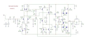
I’ll also add a second option for two diff stages in current mirrors. The second differential stage with current mirrors is made of medium power transistors,
The second signal path through the diff stages is essentially a current generator for the driver stage, which controls the IRFs.
with the same output power of 100 watts into a 4 ohm load,
Gain open loop 104dB, the distortion is already greater and amounts to 0.004% (20 kHz) and 0.002% (1 kHz).
Feature option 2 is a symmetrical limitation of the signal, the remaining features of the output stage are similar to the option from the 1st post.
P.S. added scheme Variant 2 to the 1st post
Attachments

Last edited:
Varient 2 is like my "symasui" (below) , VERY low THD - < .5ppm-20k. nice design like this should use TTA/TTC toshiba to-126's , 340/350?? ha ha !P.S. added scheme Variant 2 to the 1st post
faster/low cob. Actually , this is the classic "Hitachi" IPS...
OS
Attachments
Option 2 is an option for a driver cascade that operates in class A, which controls IRFs. I often see variants of circuits with 2 diff cascades (for example, Holton) where the driver for controlling IRFs is built as a push-pull and then loaded with excess current in class A. - I have listened to such options. Option 2, which is posted for me, is more preferable in sound.Varient 2 is like my "symasui" (below) ,
What you posted in the attachment is nonsense for me, despite all the beauty of the drawing, cascode assemblies in such variants do more harm than good, and besides, there is also correction by the Miller C7. The methodology for increasing the linearity of cascades for sound amplifiers arose much later than the Nitachi amplifiers were designed; I’ll try to imagine what it looks like in future versions. There will be a lot of them in this topic.this is the classic "Hitachi" IPS...
OS
to be continued.
Last edited:
Look:
1. Tracking power is effective for input stages on jfets or when the input stage operates in microcurrent mode with high gain, which is used in operational amplifier technology. What is the effectiveness in your case? this is a big question.
2. This frequency must be more than an octave lower than the unity gain frequency of the device. This is for better dynamics.
3. the nonlinearity of Q4 Q5 and Q16Q15 occurs due to the nonlinear load Q6Q7 and Q13Q14, the shape of the load is a hyperbola in the audio frequency band. If we were building an FM radio receiver, then we would not be interested in nonlinearity in the frequency band 800Hz-3kHz, but the power amplifier is not a radio receiver. In fact, Q6Q7 and Q13Q14 “hold the throat” of Q4 Q5 and Q16Q15 and do not allow them to operate linearly in the audio frequency band; to do this, it is necessary to unload these cascades with a resistor, or even better, design a “broken” cascade, which is equivalent to the unloading resistance.
3. The illogicality of the 2-pole correction in this cascode lies in the fact that only Q14 works in amplification at the correction frequency, it is because of this that C6 has to increase the capacitance relative to C7, i.e. the second order will be determined exclusively at the frequency that will determine the capacitance of C7. If you switch the Q16 to linear mode C6 and C7 will become equal denominations.
4. D5D6 lacks a resistor in series to limit the short circuit of the diff cascade when these diodes are triggered. It is advisable to connect D5D6 in parallel with C10, then R20 will soften their operation.
I gave you an example of why, during test comparative listening with tube devices, audiophiles cringe at the sound of a transistor amplifier, even if it has low distortion and high power...
Attachments
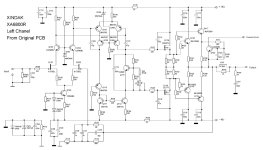
Yes, this is probably for Variant 2, this was mentioned in post 8, but there is a significant difference in Variant2 - this is common-mode control of the Driver.This is a HOLTON modification amplifier schematic
To be fair, autor Flickinger developed 2 complementary diff stages long before Holton; Flickinger also introduced common-mode stabilization of the input diff stage, which significantly increased the linearity of the circuit; Holton no longer had this - he simply weakened the gain by loading the input pair onto resistors.
There is no point in commenting on your sсhema in attachment; the output of a cascode driver loaded to a load high input impedance of the driver with increased junction capacitance almost always creates nonlinearity. with Miller correction, this is not noticeable in other options - for linear circuits this is unacceptable.
Henna you try change of more speed transistors for yours V stage ? Some like 2sd667/647
MJE350 is lower speed than 2sd667/647
MJE350 is lower speed than 2sd667/647
power dissipation for Q7/8/10/11 in the circuit in Variant 2 is 0.2 watts with a power supply of +/-36 volts, 2sd667/647 that’s max 0.9 watts, сan try.MJE350 is lower speed than 2sd667/647
If I have their models, I'll try them tonight. But you can select elements according to your taste.
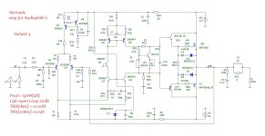
While I was having lunch at work I sketched out Variant 3.
circuit features:
1. minimum power supply +/-45 volts
2. only one gain stage (broken cascode)
3. power hybrid darlingon output in push-pull mode
4. input stage in linear mode thanks to resistors R17R21 in the Q7Q9 emitter circuit
5. circuit R18 C5 eliminates the occurrence of positive feedback at frequencies above 50 MHz
6. progressive correction.
X1 adjust 0 at the amplifier output
X2 initial current 80mA
Please note The Thiel coil is closed by a resistor R31 with a nominal value of 2 Ohms, the current through this coil will be 1.8 times higher than through the speaker, so it would be advisable to make it from a wire 1.5 - 2 mm thick.
1 watt of heat is dissipated on transistors Q11 Q12, therefore it is better to place these transistors on a separate radiator 40 cm2, or on a common radiator with output transistors.
should appeal to audiophiles as there is only one voltage gain stage and one composite push-pull output stage.
Attachments
Last edited:
ZTX653/753 better than 2n5551/5401
And more power for bass loads when listen music
Also good medium transistors is a hitachi 2sd667/2sb647 but his a more warm sound when listening
Anyway if you change transistors type
you need change resistors for balance currents in V stage
And more power for bass loads when listen music
Also good medium transistors is a hitachi 2sd667/2sb647 but his a more warm sound when listening
Anyway if you change transistors type
you need change resistors for balance currents in V stage
It is called folded cascode: https://electronics.stackexchange.c...sed-to-raise-the-output-resistance-of-the-pnpWhile I was having lunch at work I sketched out Variant 3.
circuit features:
1. minimum power supply +/-45 volts
2. only one gain stage (broken cascode)
3. power hybrid darlingon output in push-pull mode
4. input stage in linear mode thanks to resistors R17R21 in the Q7Q9 emitter circuit
5. circuit R18 C5 eliminates the occurrence of positive feedback at frequencies above 50 MHz
6. progressive correction.
X1 adjust 0 at the amplifier output
X2 initial current 80mA
Please note The Thiel coil is closed by a resistor R31 with a nominal value of 2 Ohms, the current through this coil will be 1.8 times higher than through the speaker, so it would be advisable to make it from a wire 1.5 - 2 mm thick.
1 watt of heat is dissipated on transistors Q11 Q12, therefore it is better to place these transistors on a separate radiator 40 cm2, or on a common radiator with output transistors.
should appeal to audiophiles as there is only one voltage gain stage and one composite push-pull output stage.
thank you, I call this a “broken cascode”; the topology is clearer this way, and the adjective does not stop this cascade from being a cascode.It is called folded cascode
Even through some of your "improvements" (diodes) - I like , that sim and it resulting IPS even beats the Wolverine in the PPM category. CloseWhat you posted in the attachment is nonsense for me
to the Halcro. I suppose the halcro's design is also nonsense.
.04% 20K - for audiophiles ?? That is where I look for what is "broken" (or non- linear) in the design. A good design stays <30 PPM right up to clip
at all audio freqs. PS - you might not really "hear" .04% depending on where the non-linearity is in the circuit.
OS
Last edited:
- Home
- Amplifiers
- Solid State
- Amplifier with output power transistors IRF240/9240