Don't know if this is already covered, but you could limit the output transistor currents to say 35A independent of the protection.
The short delay before the protection activates is then taken care of, while 35A is unlikely to limit signal current. If it does, just make it 40A ;-)
Jan
The short delay before the protection activates is then taken care of, while 35A is unlikely to limit signal current. If it does, just make it 40A ;-)
Jan

Almost forgot:Music waveforms are not symmetric by any means though. Lots of 2nd harmonic out there....
This protection does nothing if load impedance is normal.
If signal is, say, 5:1 assymetrical (just to use a number), positive half will slam against + rail way before bottom half clips, with no further effect.
Now into a short, any negative swing will do.
That's one reason SS amps are SO easily blown by shorts (in absence of protection), any voltage source tries to put out infinite Amperes into a short.
The full rail voltage + full current (way more than expected into a load) combination is DEADLY.
Tubes on the contrary are self current limited by design , have no second breakdown mechanism and worst case they red plate, usually survivable.
The OP's problem is that the VAS current is unstable. That leads to the Vbe multiplier voltage being unstable, the output transistor bias being unstable, and the output transistors burning out. He needs to fix the source of the problem.
Ed
Ed
The problem with conventional VI limiting is that it doesnt do nothing if the load impedance is low but normal. At very high impedance is does do nothing. But as you get to within an order of magnitude of the limit value, the protection circuits conduct just enough current off the VAS to be annoying. Open loop gain starts dropping, distortion rises, long before an actual limit is reached. And if local loop stabilization is used in the limiters, it loads down the circuit at high frequency during normal operation. All of this results in an amplifier that has worse performance with the limiters in place than without.
If protection matters more than THD20k, you just live with it. If the amplifier performance under normal use matters more, you live with the risks of removing or relaxing the protection. The best of both would require real-time software control, calculating the VI product on the fly, and applying appropriate input processing independent of the global NFB. It’s a lot more work to do something that is in principle very simple.
If protection matters more than THD20k, you just live with it. If the amplifier performance under normal use matters more, you live with the risks of removing or relaxing the protection. The best of both would require real-time software control, calculating the VI product on the fly, and applying appropriate input processing independent of the global NFB. It’s a lot more work to do something that is in principle very simple.
Looong time ago I designed an analog circuit modelling the SOA of output devices of a power amp.
The SOA sim output drove the protection circuit.
Worked very nice; it let anything go as long as the SOA wasn't exceeded, so it automagically took account of load impedance and phase angle.
It was published in https://cc-webshop.com/collections/books-audio/products/audio-amateur-power-amp-projects but I will see if I can find it on my PC.
Of course, these days I would use a controller to do the calculations digitally rather than analog computing.
Can't find it now, but this was the concep:
Cut the SOA in a number of sectors that are relatively straight line approximations.
For each sectors determine the time in us or ms that that particular V*I can be allowed.
If the allowed time is exceeded, shut down.
Continuously calculate V*I which is the instanteneous power dissipation.
Determine which value of the SOA curve is appropriate for the current V*I value, and count down the allowed time.
You can do this with charging or discharging a cap.
All this is done on a continuous basis, so the calculated V*I dynamically adjust the countdown (cap charge or discharge).
Worked like a charm.
Edit: here's the content list: https://www.hificollective.co.uk/books/power-amp-projects-book-2007.html
The articles are the New Power Amp Alternatives duo.
Jan
Last edited:
I have used this scheme for about 30 years. It saved the amplifier once or twice. When the sum of the currents through the output MOSFETs gets too high, Tr20 and Tr19 latch and turn off the output until you turn off the amplifier for some time. This has only happened when there was a short in the output wiring.

Cool. The schematics here are starting to puzzle me. Thanks! @MarcelvdG @jan.didden
@Easyamp. Just to answer your question on howto make it cut current faster. The way I see it: Each transistor to turn on or off is some capacitance to charge or dischage which takes a little bit of time. To reduce that time, make sure the transistors doing the turnoff can pass lots of current. The higher the current spike, the faster the turnoff. Next just minimize the number of stages it takes before shutdown reaches the power transistors.
Like youre doing its a good idea to latch off the whole amp from the ltp's. Do check how the output responds when doing so! Does it mute neatly when turning off?
I would additionally short the bias of your ops BUT sense current directly from the emitter resistors on P and N sides. (Shortest "turnoff path") This looks like a traditional current limiter lol. Like jan suggested, set these to limit at a high current. Your ops will see a big current spike before the latch turns off the amp. Just implement the current limiter such that we survive that spike. (Said limiter may need some resistors and diodes to make sure it doesnt mess with linearity and turn out to be VI limiter you set out to avoid)
Currently im working on a mosfet relay with current sensing. (Also to avoid the VI limiter) It has a latch that can handle high current peaks to pull down the gates of the mosfets pretty darn fast. It still passes 40 amps for 1us but the OPS shouldcould survive that.
Hope all this helps a little, all the best,
Ruben
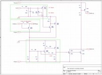
Dead end? How about instead of a somewhat voltage dependent current limiter, you use a current dependent voltage limiter. Suppose the clipping voltages respond to the current through the OPS devices. Perhaps something like this could work. Q29 is sensing output current through the 50mOhm drain resistors and outputs a small signal proportional to output current. Q33 now gives it some gain and develops the clipping voltage over the 8k2 resistor R112. Q25 essentially buffers the clipping voltage and D3 connects it to the VAS output. Values are not final but I like this circuit and Ill probably implement a version of it in future builds.
Cheers!
.png")
.png")
.png")
Cheers!
Attachments
Maybe you'd be interested in a complete system with component value calculations against the output devices SOA.
Jan
Jan
With lateral FETs you can just use a zener across the gate-source to limit the drain current - probably one of the reasons they are so robust compared to BJT output devices. You just make sure the current limit is enough to pop the fuses before the devices cook themselves.
Personally I've not ever managed to damage a power amplifier output transistor, but a DC offset protection relay for the speakers is something I quite like the idea of, plus a fuse I guess, for the keen.
I've seen clipping fry a few tweeters though.
I think there is a 'law of diminishing returns' with protection, I'd say GNFB and grounding schemes are more serious for audio in general. For bombproof stuff I would suggest making the devices bigger and the PSU smaller until that inherent balance of 'indestructible' is reached, MOSFETs it seems can be added without many limitations - a bank of lateral MOSFETs would be hard to kill 😀
You know what? If you look back at early I-V protection schemes, you'll see some also referenced to a 0V point and delayed the trip with capacitance. These two things decreased sensitivity to current at higher output voltages, and allowed for peak currents. Basically allowing for a measure of reactive reasonable speaker loads and peaks in the program material. All power supplies have fuses (or should), but they protect the supply in case you do have supply or output failure. Look at some classic Marantz schematics where we had adjustable SOA protection. These protection circuits didn't interfere with the sound unless you had stupid speakers.
About blowing stuff up. In my nearly 50 years of service, either the person really deserved to have blown the output stage (and I was impressed), or it was a marginal design. Heat buildup blew stuff up as often as a short for example. Today's cheaply made amplifiers are far more at risk, we just used to make sure we had lots of headroom and heat sink available. When you are DIY, the cost of another pair of outputs isn't great.
Clipping and blowing tweeters. Yeah ... you deserve it. CDs (Cadmium photo cell) cells across the input can be used to compress the input. You're distorting anyway, so don't worry about getting fancy. Carver did this along with many other brands - not a bad idea.
You can't really protect against stupid. They will always find a way. Although, Carver amps would shut down the power supply. Very rare to blow an output stage, unless you cooked them to death, running highs or mids only at high power would do that. The commutators were timed for full range or bass. Can you imagine 375 watts per channel of mids or highs only?
Yes I can imagine 375 watts per channel of mids or highs only, going directly into 1.4” exit 3” coil drivers. 20 kHz capable commutators aren’t all that hard to do. Maybe not a full 375 watts of long term average, but it will approach 100.
And the amount of degradation at normal levels due to the use of conventional VI limiters is no big deal in such applications. Distortion gets down into the .05% range (below clipping) and any lower is a don’t care. Slowing them down where they take a couple milliseconds to kick in doesn’t seem to cause any trouble with blown outputs either.
Amps that get used at “stupid” levels just have to be engineered for the job. Enough SOA and VI limiting to enforce it, enough heat sink for the waste heat generated, power supplies strong enough to take it for hours. They quit making that stuff entirely in the early 80’s. But I didn’t. Other than loud fans, it sounds good enough for hi-fi, too.
Well, the commutator hold up was timed for bass. So the power supplies hang up to the higher voltage levels and that causes excessive dissipation. The heat sinks were not designed for that. Back in the 80's, no. Not at reasonable prices anyway. MJ15024 and MJ15025, and those are not slow devices.
I agree, the way Marantz and others implemented I-V limiting did not interfere with normal program material or speaker loads. 0.05% THD was reasonably good back then, many amps didn't come close if they were high power. At high powers, the speakers contributed much higher distortion. I-V limiters with good designs did not contribute to distortion.
Well, yes. You're bang on. However that is expensive, and home amps would be priced out of the market. PA amps were generally not suitable for listening at home. Once forced air cooling was introduced, it really pushed those amps out of the home. On the flip side, few cleaned the filters and many of those amps died a nasty death. It was like cleaning out a vacuum cleaner when you serviced them. Bar amps were even more "special".
The Yamaha PC2002 is an excellent amp for home use. They should have simply packaged it differently and sold it to the home market. But, they are all road scarred.
Hi Jan,
Clippers and compressors always have to begin acting at lower levels. Why not just stick some form of clip lights on the front panel? No excuse for the operator then, fair warning.
You can't protect stupid from stupid. But, if you must, I guess the Klever Klipper is a decent option.
Clippers and compressors always have to begin acting at lower levels. Why not just stick some form of clip lights on the front panel? No excuse for the operator then, fair warning.
You can't protect stupid from stupid. But, if you must, I guess the Klever Klipper is a decent option.
- Home
- Amplifiers
- Solid State
- New approach to amplifier protection