Greetings Friends. I've built a nice little amp

Hammond 270DAZ PT, 6CA4 rectifier, EL84 output tubes, EDCOR GXSE15-5K OPTs. Currently using 6DJ8 as driver tube but I'd like to be able to use any b9 tube as I also have 6N1P, 6N6P, 6N23P etc I would like to try out. The power supply is borrowed from @Suncalc Marblewood amp:


There's a switch on top to choose Pentode or U/L, and a pair of DPDT switches on the back to control FB and the v1 bypass.
I wired up the amp with a Suzuki circuit I found over on Single-Ended.com

with the 33k resistor before the driver supply cap, the supply voltage is quite low, I measured ~32v on the plate of the driver tube. The amp sounds fine, but I'm wondering if the driver tube should be operating at a higher voltage. Perhaps a larger 1.2k K resistor and a smaller resistor for the supply would get the operating point closer to the middle of the load line.
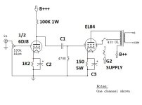
But How do you calculate that coupling cap? the grid leak for the power tube sets the impedance for the stage? this is where I'm lost. And the bypass caps? Here's a circuit schematic with the unknown values:

Hammond 270DAZ PT, 6CA4 rectifier, EL84 output tubes, EDCOR GXSE15-5K OPTs. Currently using 6DJ8 as driver tube but I'd like to be able to use any b9 tube as I also have 6N1P, 6N6P, 6N23P etc I would like to try out. The power supply is borrowed from @Suncalc Marblewood amp:
There's a switch on top to choose Pentode or U/L, and a pair of DPDT switches on the back to control FB and the v1 bypass.
I wired up the amp with a Suzuki circuit I found over on Single-Ended.com
with the 33k resistor before the driver supply cap, the supply voltage is quite low, I measured ~32v on the plate of the driver tube. The amp sounds fine, but I'm wondering if the driver tube should be operating at a higher voltage. Perhaps a larger 1.2k K resistor and a smaller resistor for the supply would get the operating point closer to the middle of the load line.
But How do you calculate that coupling cap? the grid leak for the power tube sets the impedance for the stage? this is where I'm lost. And the bypass caps? Here's a circuit schematic with the unknown values:
Attachments

What extra information do you need to use calculators like these?
I'm sure there are more calculators online - I just pulled up the first 2 I came across.
I'm sure there are more calculators online - I just pulled up the first 2 I came across.
What about old school?
https://www.diyparadise.com/tubeloadline/tubeloadlines.html
About output coupling capacitor, the general equation look like this:
F = 1/(2 * pi *RC) solve for C you get this:
C = 1/(2*pi * F * R) ≈ 0.16/(F*R);
Where
R - Resistance seen by the capacitor
F - The lowest desired frequency you want to amplify
I don't understand the significance of the numbers. what's the difference between a 1uf cap in C1 and a 0.1uF? what role does the grid leak resistor play?
How do I determine the required gain for this output stage? how do I bias the preamp tube to best deliver that signal? once I've set the operating points, how does the bypass cap deliver the required frequencies and how is that calculated?
How do I determine the required gain for this output stage? how do I bias the preamp tube to best deliver that signal? once I've set the operating points, how does the bypass cap deliver the required frequencies and how is that calculated?
Will be good if you read something before to ask, look for information using Google.
Gid leak resistor purpose: It helps prevent high frequency parasitic oscillation in the tube itself.
Gid leak resistor purpose: It helps prevent high frequency parasitic oscillation in the tube itself.
What about old school?
https://www.diyparadise.com/tubeloadline/tubeloadlines.html
About output coupling capacitor, the general equation look like this:
F = 1/(2 * pi *RC) solve for C you get this:
C = 1/(2*pi * F * R) ≈ 0.16/(F*R);
Where
R - Resistance seen by the capacitor
F - The lowest desired frequency you want to amplify
R is the input impedance where is connected the output capacitor
F usually 20Hz
Hey thanks for the replay, but I'mma need a little more to go on...
Right now, I think knowing the difference in selecting a .1 cap over a 1uF for coupling is the least of your issues in this amp. If you do the math on the circuit load for the Power Tranny (PT) you'll see that rated for 104mA is being asked to supply upwards of 135mA. The typical biasing for a 6DJ8 runs it at 15mA per section and your 6BQ5's are biased at 53mA each. The PS circuit has 500R of resistance which is about 3x what other traditional 6BQ5 SE amps will use. You can run those ~300v plus, on the plate with cathode biasing.
Thanks for taking a look. I had been under the assumption that the driver tube was using no more than 5mA total, prob need to find a different driver tube. 180 or 200 ohm k resistors on the power tubes might free up some mA as well.
resistance in the power supply is another murky area for me - how do you determine it here, and what can be done to improve it?
resistance in the power supply is another murky area for me - how do you determine it here, and what can be done to improve it?
Dubadub - looks like you need to know Ohms Law inside out, all the permutations. You can't work with tubes or electronics in general without Ohms Law. And with tubes you also need all the data sheets which you can find on Franks Tubes. In particular the maximum ratings. OK, Tubelab can blow things up but he knows what he's doing!
https://frank.pocnet.net/sheets/030/e/EL84.pdf
https://frank.pocnet.net/sheets/030/e/EL84.pdf
The max available power supply voltage shown is 272 Vdc. The driver plate load is 100k. The absolute max current draw per driver is 2.72 ma if the driver shorts to ground. Under normal conditions where the driver plate voltage is approx half of B+ it's probably closer to 1 ma.the driver tube was using no more than 5mA total,
From the EL84 cathode voltage each output tube draws 53 ma combined plate and screen current. That's still on the hairy edge of the PS transformer rating. It was a long time ago but I think that's the same Hammond that pulled the magic smoke trick on me in a Mullard 3-3 build.
Oh yes, the driver is being starved. Haven't looked at what the 6DT8 or AQ8 uses normally. This would use a 12AX7 well, I think.
This circuit was designed for a 6DT8/12AT7 seeing that supply and 100k Rp and that Rk, too. Well, then the overkill on PS filtering needs sorted. Get the B+ up and the 6BQ5's idle current down a bit and all will be copa...
Hey thanks for the replay, but I'mma need a little more to go on...
The Valve Wizard has always been helpful for me. https://www.valvewizard.co.uk/Common_Gain_Stage.pdf
I've read Merlin's book, some of it stuck. What I'm after is an explanation of how the driver tube interacts with the next stage, what happens to the signal.
The amplified signal comes from the plate, is loaded by the plate resistor, passes thru the coupling cap, loaded by the grid leak resistor, and then encounters "basically infinite" resistance at the grid of the next tube. Ra is determined by the gain requirements
Then we've got to consider the R-C filter's effect on the signal, is there a pole that will kill audible frequencies?
The value of the coupling cap and following grid resistor form a high pass filter that will set a 3dB pole for a 1st order filter. I use an online filter calculator I saved to do the dirty work, but after you do a few of them you realize that most of the common values will give you a reasonable pole of ~10Hz. It's better for amplifier stability to cut the inaudible points so I choose a higher start freq. than most. If you want bass boost use an EQ or the bass knob. Keep in mind that these DIY amps don't provide any loudness compensation in the volume controls like common SS amps. People think lowering the rolloff point with a big coupling cap gets them better bass but if it's not in the music anyway, there's nothing for the lower rolloff to pass..
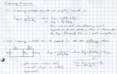
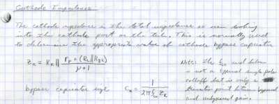
Here are the basic formulations for figuring cathode impedance (hence cathode bypass), coupling capacitors, and high frequency rolloff due to Miller capacitance. Note that going too large can lead to blocking distortion in overdrive conditions. Personally I like to set low frequency transitions between 3Hz and 5Hz.
Attachments
- Home
- Amplifiers
- Tubes / Valves
- How do I calculate the capacitor values in a SE amp? Coupling + k bypass