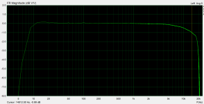
I have a question on frequency response of the Kegger/Blueglow KT88 design which I've built. It kind of seems to roll-off quite early at the high end and by 15kHz it is already 1dB down (the testing software I've used ends at 20kHz). Probably not the end of the world but just curious if this might be the fault of the output transformers. Could you suggest some (hopefully not so complicated) testing procedure how to confirm/eliminate OPTs impact on the FR I see? I am new to DIY tube amps so hope my question makes sense.. Thanks

Attachments
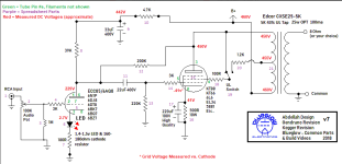
this build is based on blueglow YT series, the schematics are on blueglow's site - https://drive.google.com/drive/folders/17jRI1lE_Vf9_Pq64LbT-PHy3pLpW1vuj
Attachments
Are you loading the OT secondary properly for the measurement?
To measure the signal at the OT primary (still with the proper secondary loading),
you need a high voltage differential oscilloscope probe.
To measure the signal at the OT primary (still with the proper secondary loading),
you need a high voltage differential oscilloscope probe.
maybe I should also add that this is by no means a bad sounding amp, or at least I can't hear any obvious sound issues. It's just that I would expect a completely flat FR till at least some 10kHz ... and since I have used a forum-recommended supplier of OTs I am just wondering if those OTs are not the weak spot of the whole design.
I've used 6,8ohm resistors connected to output in parallel to the connection of line-in of my sound card.Are you loading the OT secondary properly for the measurement?
To measure the signal at the OT primary (still with the proper secondary loading),
you need a high voltage differential oscilloscope probe.
and what exactly is mfr FR? the manufacturer of the OTs says they are easily 25Hz-35kHz before -3dB, can't get any more detalied specs unfortunatellyWhat is the mfr frequency response spec?
Rayma,
The primary is AC grounded at the B+ end of the winding. (Signal Grounded at the B+ end).
Therefore, Only a Single ended High Voltage probe is needed (High Voltage tip to the output tube plate; and probe ground clip to amplifier ground.
If the B+ has any significant voltage at 10kHz or 20kHz riding on it when the amplifier is putting out maximum power at 10kHz or 20kHz . . .
Then Fix the B+ filter.
A differential probe is not needed for this test.
I Have a P5200 probe, for just such testing. It is not cheap; cheap is not good, good is not cheap.
Good Differential probes are much more expen$ive.
I do not need to spend ($pend) the money for a high voltage differential probe to test vacuum tube amplfiers.
Everybody,
Do not use floating amplifiers, and do not float your 3 wire grounded scope. Safety First! Prevent the "Surviving Spouse Syndrome".
jank9,
Use a non inductive 8 Ohm load resistor on the 8 Ohm tap (or resistance to match the tap that you use: 16/16, 4/4, etc.)
Set the switch to UL mode.
Test the frequency response at the primary, using a high voltage probe.
Test the frequency response at the secondary.
Compare the difference between the primary and secondary. Most of that difference will be due to the leakage inductance from the primary to the secondary.
Set the switch to Triode mode.
Test the frequency response at the primary, using a high voltage probe.
Test the frequency response at the secondary.
Compare the difference between the primary and secondary. Most of that difference will be due to the leakage inductance from the primary to the secondary.
If you do not have a high voltage probe, then at least . . .
Set the switch to UL mode.
Test the frequency response at the secondary.
and
Set the switch to UL mode.
Test the frequency response at the secondary.
I expect the Triode mode to have better high frequency response; Versus the UL mode high frequency response.
Is that what you get?
Have Fun!
Last edited:
and what exactly is mfr FR? the manufacturer of the OTs says they are easily 25Hz-35kHz before -3dB
That -3dB at 35kHz is mathematically about -1dB at 17.5kHz, even if it's the slowest possible roll off.
Rayma,
Many output transformer's high frequency rolloff rate is 12dB/Octave (2 pole low pass filter).
Therefore, -3dB @ 35kHz would be approximately -1 dB @ 25kHz. (Not @ 17.5kHz).
And . . . that is in the transformer's favor, 25kHz @ -1dB is better than 17.5kHz @ -1dB.
Many output transformer's low frequency rolloff rate is 6dB/Octave (1 pole high pass filter).
Therefore, -3dB @ 20Hz would be approximately -1 dB @ 40Hz.
I often do not like many of the marketing groups of both output transformers and of loudspeakers.
They have something in common . . .
Many marketeers purposely hide many important specifications.
Last edited:

Guys, thanks a lot for valueable hints.
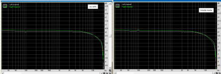
@6A3sUMMER - don't have a HV probe. I've done the UL/Triode mode test and not much of a difference - if any, the triode mode seems to have a slightly bigger drop... so the opposite of what you've expected if I got you right

@jdarg - this is at more or less mid-volume. Moving up to full volume - there is no change. the OTs are from an independent/local specialist (recommended by some of the local commuinites)
@6A3sUMMER - don't have a HV probe. I've done the UL/Triode mode test and not much of a difference - if any, the triode mode seems to have a slightly bigger drop... so the opposite of what you've expected if I got you right
@jdarg - this is at more or less mid-volume. Moving up to full volume - there is no change. the OTs are from an independent/local specialist (recommended by some of the local commuinites)
Attachments
Not sure what you mean, but I've done the same FR test for all my other amps and their graphs go flat till almost 20kHz so I guess the testing procedure is OK...Looks a lot like a 44.1ks/s sampling rate, not much like a transformer.
All good fortune,
Chris
you mean the FR of the signal comming from coupling capacitor to the first grid of KT88? I guess it should be done manually with sig. gen and scope as the signal will be too weak to drive my soundcard for tools like RMAA or ARTA?Have you confirmed a flat FR at the grid to the KT88?
So your test instrument is only a sound card output and input? And you drive the input from the speaker terminals? How do you connect it there and keep from overdriving the soundcard input? The grid voltage would be very similar to the speaker terminal levels so if you can connect to the grid you should have ample signal into the sound card. That amp is biased for low power.
For FR sweep I used my sound card and RightMark Audio Analyser program... and according to instructions you loop back the output from the amp (with 8R resistive load) to the soundcard input (appearently the RMAA soft has some overdrive protection built in). Before the amp test I've tested the soundcard itself (with loopback connection) and the soundcard itslef is OK (flat FR, low distortions, etc)
I also have a simple scope with signal generator, but that's all my equipment I am afraid. I will try with grid over the weekend...thx
I also have a simple scope with signal generator, but that's all my equipment I am afraid. I will try with grid over the weekend...thx
- Home
- Amplifiers
- Tubes / Valves
- Kegger/Blueglow KT88 frequency response