How is random walk measured, so as to be called random walk? IOW, does the measurement technique integrate or does it show essentially instantaneous detail?...a plot of a random walk...

try plucking a string with sub ms accuracy, good luck, And I'm speaking as a musician here 😀Good is that none of these "timing errors" as any meaning whatsoever to timing as in "plucking a string" ;-D
//
HINT: copied over from the original thread. To make the discussion not loose the last post by @TNT
Marcel, if you have time maybe you could shed some light on how the used fft window function does affect frequency resolution. as the window is a function of LEVEL vs TIME - i get the level part of it, it will affect actual level measured. but how does it affect frequency resolution? I'm pretty sure there is a sound mathematical base for this, but as of now I simply don't understand it.Close-in phase noise is nothing else than slow random clock frequency variations, and you try to make your measurement insensitive to small clock frequency inaccuracies.
I don't understand why you dislike Hann windows. OK, you need twice the number of samples for the same frequency resolution, but you don't have to worry anymore about asynchronous signals and clocks and about the fact that anything involving sigma-delta modulation is not exactly periodic.
FFT stands for Fast Fourier Transform, which is an accelerated version of Discrete Fourier Transform (DFT). Despite the name Fourier Transform (FT), DFT essentially implies Fourier Series, where the signal needs to be periodic. Fourier Transform has no such restriction. Integration over an infinite range is impossible, so window functions are employed to limit the integration range. However, window functions in DFT, being Fourier series, are used to ensure periodicity.
Generally, an audio signal is not periodic. Even a sine wave is typically non-periodic within the calculation range of FFT. Hence, a window function is used to forcibly make it a periodic function. As a side effect, frequency components that shouldn't exist appear on both sides of the correct frequency. Therefore, this smearing becomes a significant obstacle when examining phase noise. This smearing is minimized when using a Hann window.
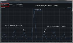
I synchronize ADC and DAC to measure without using window functions. In other words, if supplying a periodic signal, window functions are unnecessary, and there is no smearing. In such cases, you can use a rectangular window. In FT and DFT (FFT), rectangular has entirely different meanings. In FT, it's one of several window functions, while in DFT, it means no window function. Interestingly, this point is often omitted in textbooks.
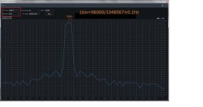
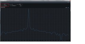
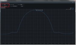
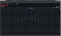
A periodic signal implies multiples of bins. Therefore, 1 kHz becomes 999.01 Hz. Pic#3 to pic#5 show the FFT of signals with preserved periodicity, where rectangular can be used. This results in a perfect FFT without smearing. Even with the least smearing using Hann, there are still considerable additional components. In actual signals with residual noise, the difference is not as pronounced (pic#1 and pic#2), but for observing phase noise, rectangular is preferable.
Generally, an audio signal is not periodic. Even a sine wave is typically non-periodic within the calculation range of FFT. Hence, a window function is used to forcibly make it a periodic function. As a side effect, frequency components that shouldn't exist appear on both sides of the correct frequency. Therefore, this smearing becomes a significant obstacle when examining phase noise. This smearing is minimized when using a Hann window.
I synchronize ADC and DAC to measure without using window functions. In other words, if supplying a periodic signal, window functions are unnecessary, and there is no smearing. In such cases, you can use a rectangular window. In FT and DFT (FFT), rectangular has entirely different meanings. In FT, it's one of several window functions, while in DFT, it means no window function. Interestingly, this point is often omitted in textbooks.
A periodic signal implies multiples of bins. Therefore, 1 kHz becomes 999.01 Hz. Pic#3 to pic#5 show the FFT of signals with preserved periodicity, where rectangular can be used. This results in a perfect FFT without smearing. Even with the least smearing using Hann, there are still considerable additional components. In actual signals with residual noise, the difference is not as pronounced (pic#1 and pic#2), but for observing phase noise, rectangular is preferable.
Attachments

Last edited:
It depends, I would say. If the DAC and ADC chip's Vrefs are compatible and power sequencing and startup time are OK for both, then why not? Especially for DAC+ADC intended for sync'd loopback measurements the (almost 100%) sync'd Vrefs really help to suppress DC/LF gain instability.Having same Vref on both ADC and DAC is not feasible in practice.
I modded an existing product based on AK4493 and AK5574 to share one common Vref across chips and channels. Works perfectly... provided that the reference is fast and stiff enough (LT3045). Practically, Vref becomes a power plane in the layout.
I know that it is good recommended practice to have individual Vrefs per chip and channel to eliminate any crosstalk. However, in a compact multilayer design with a good reference one can get away with a shared Vref, trading a bit of crosstalk for a 100% stable unity gain factor through the ADC-->DAC loop. All the fluctuating gain errors are canceling each other pretty well because they are fully matched.
As for the main topic, I think the best we can do on the physical level is having an excellent master XO right between the chips and shortest possible feeds to the MCLK pins, RF-style.
But DAC and ADC internal noise mechanisms on top of a given and matched input pin signal quality will be different so they have no real chance for cancelling. That's the final brickwall as far as I can see.
That common MCLK must still be as stable as it gets because a wandering MCLK is conceptually equivalent to a DUT modulating its own frequency response, all time constants modulated by the same factor. If one is measuring a high-pass then the slope slightly "wiggles around" and a single tone in the FFT will look like if it were modulated. Same goes for low-passes, starting with the analog filters of DAC output and ADC input.
I don't know about other members but I using these measurements mainly for comparing DACs. So DAC and ADC are on separate boards which makes having common Vref practically infeasible.It depends, I would say. If the DAC and ADC chip's Vrefs are compatible and power sequencing and startup time are OK for both, then why not? Especially for DAC+ADC intended for sync'd loopback measurements the (almost 100%) sync'd Vrefs really help to suppress DC/LF gain instability.
I modded an existing product based on AK4493 and AK5574 to share one common Vref across chips and channels. Works perfectly... provided that the reference is fast and stiff enough (LT3045). Practically, Vref becomes a power plane in the layout.
My understanding is that the closer you get to the fundamental the phase noise is mostly random walk or flicker noise both of which cause random fluctuations. "Random fluctuations" and "displaced by about the same amount" do not rhyme.
Suppose you have a clock generator that ideally should produce clock periods of equal length, but actually produces clock periods that have an independent identically distributed Gaussian variation with a standard deviation of 2 ps. The amount that the clock edges are ahead of the ideal location in time is then a random walk. A frequency detector connected to the clock signal should produce a white output spectrum: as the length of each clock period varies independently of its colleagues, the momentary frequency must have a white spectrum - corresponding to a 20 dB/decade roll-off with the distance from the carrier on a phase noise plot.
I've written a makeshift Pascal program to generate four of the random walks showing the amount that the clock edges are ahead of the ideal location in time, and plotted them with Gnuplot, over 200 000 clock cycles:
As you see, they are all different, they all have local variations, but still, thousands of adjacent clock periods have roughly the same distance from the y = 0 line. For example, on the blue curve, the 140000th to 160000th rising clock edges are all ahead of the ideal clock by (700 +/- 100) ps.
As was explained e.g. here in post #42 there are loads of noise sources some from the oscillator and some from external sources. Many of these noises are random which means that they can occur anywhere in the above plot. But this is not only about oscillator noise as DAC and ADC have noise sources of their own that impact timings. It may be the some of the timing errors are cancelled but hardly all.
Marcel, if you have time maybe you could shed some light on how the used fft window function does affect frequency resolution. as the window is a function of LEVEL vs TIME - i get the level part of it, it will affect actual level measured. but how does it affect frequency resolution? I'm pretty sure there is a sound mathematical base for this, but as of now I simply don't understand it.
Maybe I was sloppy with the terminology, but what I meant is that a Hann window (often incorrectly called a Hanning window) mixes some of the signal to one frequency bin above and below the actual frequency. As a result, you need larger frequency distances or smaller bins to clearly distinguish spectral peaks from each other, compared to the purely periodic case with rectangular window.
Basically, a DFT calculates a sum of sines and cosines (or equivalently complex exponentials) that pass through the data points. So when you have N equidistant samples with distances of Ts between them (*), it calculates sines and cosines at frequencies that are integer multiples of 1/(N Ts) that together sum up to the sample values. As a result, the DFT always describes a waveform that is periodic in N Ts. When the actual signal frequency is such that you can't fit an exact integer number of cycles in N Ts, the DFT gives a Fourier series of the periodic continuation of the samples, that is, the samples are repeated over and over again with jumps where the waveform goes from the last to the first sample, as shown in the first of the articles Mark linked to. Those jumps with repetition rate 1/(N Ts) usually mess up the spectrum completely.
Windowing tapers off the signal near the first and last samples to make these jumps smaller, so they don't mess up the spectrum nearly as much as they do without windowing. My favourite is the Hann window, which is just a sum of a constant and a cosine. It goes to zero at the beginning and one sample time past the end of the data and has its maximum halfway. The samples are multiplied by the window before the DFT is calculated.
That means that basically, the signal gets multiplied by the sum of a constant and a cosine wave with frequency 1/(N Ts). Multiplying with a cosine wave is roughly what we have been doing in superheterodyne radios since 1919 to convert the received frequency to the intermediate frequency. Hence, some of the signal gets shifted up and down in frequency by 1/(N Ts), which is one frequency bin.
When I simulate sigma-delta converters at work, I usually choose a signal frequency such that an integer number of periods fits in N Ts and use a Hann window anyway. The reason for that is that sigma-delta converters are normally designed to be either chaotic or at the edge of chaos, so their output signals are never purely periodic. I suspect @bohrok2610 and @xx3stksm get away without windowing because the non-periodicity mainly shows up in the ultrasonic quantization noise - presumably their reconstruction filters suppress that sufficiently.
(*): Statisticians would call it a sample of size N rather than N samples.
As was explained e.g. here in post #42 there are loads of noise sources some from the oscillator and some from external sources. Many of these noises are random which means that they can occur anywhere in the above plot.
The timing errors of the individual periods in the plot of post #50 are also random. They just accumulate.
But this is not only about oscillator noise as DAC and ADC have noise sources of their own that impact timings.
Which don't normally dominate the close-in phase noise. The oscillators do that.
It may be the some of the timing errors are cancelled but hardly all.
That already means your measurement method is flawed, unless you can show that the cancelling errors are negligible.
Of course the whole discussion is largely academic, because close-in sideband noise is usually determined by voltage reference noise - but we already discussed that.
Of course even with synchronous clocks it is better to use windowing.I suspect @bohrok2610 and @xx3stksm get away without windowing because the non-periodicity mainly shows up in the ultrasonic quantization noise - presumably their reconstruction filters suppress that sufficiently.
Here is graph of asynchronous clocks (orange) vs. synchronous clock. Both with BH7 windowing.
These are not measurements of oscillators but DAC output at fs/4 sampled by ADC. Without having detailed information on the inner workings of these DACs and ADCs I would not draw such conclusion.Which don't normally dominate the close-in phase noise. The oscillators do that.
Measurement method of what? I have said many times that these are not absolute measurements and I only use these for comparing DACs. I don't see how the cancelling would be wildly different between DACs.That already means your measurement method is flawed, unless you can show that the cancelling errors are negligible.
And the 2 first graphs in https://www.diyaudio.com/community/threads/phase-noise-in-ds-dacs.387862/post-7063038 are with same DAC and ADC but using different clock. There is a visible difference in phase noise which indicates that cancellation does not fully happen.
Just for clarity, when you write DAC, do you mean a thing that includes one or more clock generators and a voltage or current reference? Or do you see the clock generator as something separate that is not part of the device under test? In the latter case, synchronizing clocks is the logical thing to do, of course.
With DAC I mean a complete DAC board with voltage reference, other supplies and analog output but not clock generators. DAC clock comes from USB-I2S board, ADC board or separate clock board. USB-I2S board clock can be either stand-alone or provided externally from ADC board or from separate clock board.
So in the above measurements in asynchronous clocking DAC uses clock from USB-I2S board and ADC uses its own. In synchronous clocking both DAC and ADC use the clock from ADC board or clock from separate board. When I compare DAC boards the clocking can be kept the same so comparisons are more meaningful.
So in the above measurements in asynchronous clocking DAC uses clock from USB-I2S board and ADC uses its own. In synchronous clocking both DAC and ADC use the clock from ADC board or clock from separate board. When I compare DAC boards the clocking can be kept the same so comparisons are more meaningful.
Cool, then we have a 57-post thread due to a misunderstanding about what comprises a DAC 😉
Guys, thanks for sharing alll that information, the reason I wanted to split off this thread was twofold. 1st solely egositic, I wanted a place to discuss this further and 2nd not to pollute the OP's thread. Achieved that. Not my work, the great moderator team did that. Put my appreciation into a PM to AllenB, several others have chimed in publicly.
All the rest of the information is greatly appreciated, need time to process or otherwise I will output possibly stupid questions. But so far, thanks to all the contributors, it's a joy to see such educated people having a nice discussion with proper tone and good educative effects for people like me. 👍👍👍
All the rest of the information is greatly appreciated, need time to process or otherwise I will output possibly stupid questions. But so far, thanks to all the contributors, it's a joy to see such educated people having a nice discussion with proper tone and good educative effects for people like me. 👍👍👍
I suspect @bohrok2610 and @xx3stksm get away without windowing because the non-periodicity mainly shows up in the ultrasonic quantization noise - presumably their reconstruction filters suppress that sufficiently.
Exactly 🙂. Unlike PCM, especially in 1-bit DSM, even if the input is a periodic signal like a 1 kHz sine wave, the output is not strictly periodic. As a result, even with synchronous sampling, it may not measure well with rectangular. However, in practical experiments, for sine waves, it generally works well. When it comes to around 5-bit DSM, this issue disappears. While this is an inherent flaw in 1-bit DSM, the required performance is not to that extent, so it's measured out of technical interest.
However, for signals like a 32-tone, there could be some issues. The likelihood of successfully measuring it becomes quite low. I think a slight decrease in accuracy even for regular audio signals. I believe it would be impossible to recognize the difference as a perceptible change in sound. Based on my experience, recognizing jitter is not possible even in vinyl, which is 100 times worse than ordinary DACs. It becomes more apparent with cassette tapes, creating a hazy feeling and a drop in clarity.
When checking jitter through the spread of skirts, it's essential to standardize FFT length, window functions, frequency range (e.g., 5Hz), etc. Synchronous sampling might not be mandatory. Comparing 1 kHz and 10 kHz and ensuring no significant differences could be a reasonable approach. It's challenging to make an absolute comparison; however, relative comparisons could provide meaningful insights.
- Home
- Source & Line
- Digital Line Level
- Synchronised AD/DA convertors and Phase Noise