Guys, I’m out of commission for a while , in the hospital. Lost 45 lbs in a total system meltdown. On the mend but dealing with PT to rebuild.
Get well soon, David. Wish you a full recovery!

Speady Recovery Dave. Been there. Not fun.Guys, I’m out of commission for a while , in the hospital. Lost 45 lbs in a total system meltdown. On the mend but dealing with PT to rebuild.
Ouch. Sorry to hear that David; all the very best for a speedy return to health.Guys, I’m out of commission for a while , in the hospital. Lost 45 lbs in a total system meltdown. On the mend but dealing with PT to rebuild.
So sorry to hear, David. Best wishes for a speedy recovery.Guys, I’m out of commission for a while , in the hospital. Lost 45 lbs in a total system meltdown. On the mend but dealing with PT to rebuild.
I’m not sure I see any positive from higher order filters. The steeper phase shift forces greater variation with position, hence messy polars. There is no particular power handling improvement to be had there.
The XA goal was to make a multi-way system with undetectable (or nearly) crossover points and as CD as possible. We displayed the product at CES in a 2 story suite and you could stand anywhere on the stairs with uniform response.
Keele Horbach is , admittedly, more scientific. I am more an impericidt, but I think the results are reasonable for XA’s complexity .
Keep working with your model .
Line arrays rule!
Thanks guys. I appreciate the positive Karma. And best wishes.
I was fit before and learning to row ( the skinny butt boats that tip over) so I think that is an aid
I was fit before and learning to row ( the skinny butt boats that tip over) so I think that is an aid
Fingers crossed, get well.Guys, I’m out of commission for a while , in the hospital. Lost 45 lbs in a total system meltdown. On the mend but dealing with PT to rebuild.
Wish you a speedy recovery David.Guys, I’m out of commission for a while , in the hospital. Lost 45 lbs in a total system meltdown. On the mend but dealing with PT to rebuild.
Regards,
WonderfulAudio
Emperecist
One who advance by dicking around. Good intuition helps.
Spell check mangled this 5 or 6 posts up.
One who advance by dicking around. Good intuition helps.
Spell check mangled this 5 or 6 posts up.

Hi,
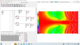
I have simulated an 11 source expanding line array in Vituixcad. There is a first order filter whose crossover frequency has a fixed relationship with the height of the array. The height of the array is twice the wavelength of the crossover frequency ie L=2 x Lambda. All drivers are in pairs except, the center one which is alone and it receives full range signal. The drivers are 3.5" fullrange units and thus CTC is 88mm. As we go up and down the height of the array, the crossover frequencies go from 3920Hz, 1920Hz, 1307Hz, 980Hz and 784Hz.
There are few things that are not clear to me.
1) The polars are good only if the center driver is boosted by 6dB, is it because it is alone while others are in pairs so gain compensation is needed?
2) There is slight loss of uniformity between 1KHz to 2KHz, how to avoid it?
3) Can the simulation be bettered in any way?
What are your thoughts?
Attached are the polar diagram and Vituixcad file in zip.
Thanks and Regards,
WA
Attachments
Last edited:
Dave has sadly passed away. I have created a memorial thread here - https://www.diyaudio.com/community/threads/david-l-smith-speaker-dave.408869/
Oof, that hurts. Easily one of my biggest inspirations. I used to work in downtown Seattle and live in the suburbs, and my favorite way to kill time while I waited for traffic to die down was to head over to the library near Capitol Hill and read David's articles and patents. They have them on microfiche on the top floor, it was like diving into a vault of knowledge.
1) The polars are good only if the center driver is boosted by 6dB, is it because it is alone while others are in pairs so gain compensation is needed?
That's right. About 22 years ago, back when Danley was discussing the Unity horns on The Bass List, something that he mentioned off hand, which I thought was interesting, was that you could basically have a 'virtual driver' composed of multiple drivers.
In the Unity, it's four 127cm drivers that largely behave as if they were a single ten inch. In the array that you designed, the driver groups operate the same way. And since there is only one of the center driver, one needs to compensate for the lack of output and sensitivity that the arrayed drivers have. (Because it's just a single unit.) Naturally, this is one of the trickiest aspects of arrays. Because you can have a single driver that's low efficiency and wide bandwidth, or a single driver that's high efficiency and low bandwidth, but you can't have both.
Hi,
I have simulated an 11 source expanding line array in Vituixcad
[...]
What are your thoughts?
Try running D2/D3 in series, D4/D5 in series, and keep the series strings in parallel with D1. For example, D2 stays where it is except its negative is connected to the D3 positive terminal, which is disconnected from the D2 positive terminal. That'll get you the +6 dB for D1 you want, no extra gain stage needed. You don't even need IIRs & multiple power amps, just slap inductors of the appropriate value before each series string.
Looking at impedances, if each driver is 8Ω, then the series strings will have an impedance of 16Ω, so D1 in parallel with D2-D3 and D4-D5 will show 4Ω to the amplifier below the lowest crossover point. You have a passel more drivers, D6-D11, and the same calculation applies except now those have three series strings in parallel for a total impedance of 5.33Ω. Two amplifiers, easy-peasy. For extra credit you could run D1 in parallel with D8-D9 (which I presume rolls off at 490 Hz) and D10-D11 (245 Hz) so the load is reduced at moderate frequencies because inductors, while the other amp can power D2-D3 (3920 Hz), D4-D5 (1960 Hz), and D6-D7 (980 Hz) at a bit wider load bandwidth mitigated by slightly higher impedance.
- Home
- Loudspeakers
- Multi-Way
- Line arrays. Understanding their behavior through simple modeling