I'm attempting to covert my speakers' crossovers from passive two-pole Butterworth to active four-pole Linkwitz-Riley characteristics. I've successfully calculated the corner frequencies with the aid of VituixCAD2 software. However, there's a problem to decide whether the polarity of either driver should be inverted or not, after converting them to active.
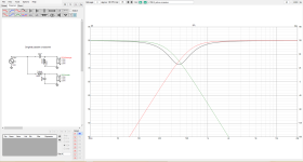
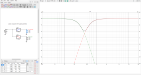
Here are the FR and Phase of the original passive crossovers.
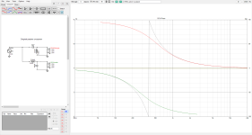
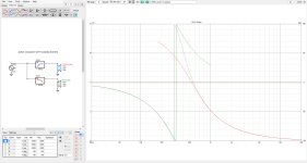
FR and Phase of active crossovers WITHOUT reversing polarity.
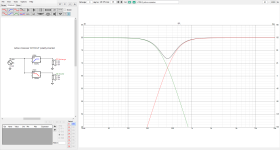
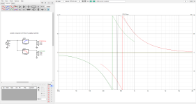
FR and Phase of active crossovers WITH reversing polarity.
Finally, the comparison
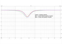
Please advice which way between inverting and non-inverting gives the closet behavior to the passive crossovers.
Here are the FR and Phase of the original passive crossovers.


FR and Phase of active crossovers WITHOUT reversing polarity.


FR and Phase of active crossovers WITH reversing polarity.


Finally, the comparison

Please advice which way between inverting and non-inverting gives the closet behavior to the passive crossovers.
I intended not to include the natural roll-offs because the passive's components of these speakers, IMHO, are quite simple and straightforward, so I assumed the natural roll-offs on those regions were nearly flat and probably could be overlooked.
I'm attempting to covert my speakers' crossovers from passive two-pole Butterworth to active four-pole Linkwitz-Riley characteristics.
are you refering to electrical or acoustic ?
presscot, is that what you meant to say? I mean ok yes, we're restricting ourselves to electrical considerations here for good reason, it is the best practical way to get to the right result.. but the electrical result is going to be varied from Butterworth in the interest of making the sound pressure response follow a Butterworth curve. Don't you agree?
@AllenB yes, that was I already stated above. I overlooked the acoustical response and would focus on electrical response instead because the original passive had simple and straightforward design. You can verify it by calculations of corner frequency and Q.
The designer seems to treat the FR of those drivers as flat at the operational region of the crossovers. Therefore, I could be trying to convert it to four-pole Linkwitz Riley curve by the use of an active crossover. Yet, the problem is the designer didn’t reverse the polarity on one driver despite the two-pole configurations, I then assumed they intended to create the “out-of-phase” condition between the two drivers. As a result, it introduced me to the question of polarity selection when transforming to four-pole crossovers.
The designer seems to treat the FR of those drivers as flat at the operational region of the crossovers. Therefore, I could be trying to convert it to four-pole Linkwitz Riley curve by the use of an active crossover. Yet, the problem is the designer didn’t reverse the polarity on one driver despite the two-pole configurations, I then assumed they intended to create the “out-of-phase” condition between the two drivers. As a result, it introduced me to the question of polarity selection when transforming to four-pole crossovers.
I always held the belief that 2nd order (2*90°) networks required polarity reversal whereas 4th order (4*90°) did not.
It's also entirely possible this conversation is well over my head.
It's also entirely possible this conversation is well over my head.
Yes that's correct..
..unless there's some delay involved, or special lobing considerations to add to the cross. Also, if there's some EQ handled asymmetrically or the converse, some unaccounted for EQ in the sim when reverse engineering.
..unless there's some delay involved, or special lobing considerations to add to the cross. Also, if there's some EQ handled asymmetrically or the converse, some unaccounted for EQ in the sim when reverse engineering.
I think you're making an incorrect assumption there. I suspect the acoustic result of your original crossover is closer to 4th-order and not the 2nd-order it looks like. This is why the original designer has the drivers connected with the same polarity.@AllenB yes, that was I already stated above. I overlooked the acoustical response and would focus on electrical response instead because the original passive had simple and straightforward design. You can verify it by calculations of corner frequency and Q.
The designer seems to treat the FR of those drivers as flat at the operational region of the crossovers. Therefore, I could be trying to convert it to four-pole Linkwitz Riley curve by the use of an active crossover. Yet, the problem is the designer didn’t reverse the polarity on one driver despite the two-pole configurations, I then assumed they intended to create the “out-of-phase” condition between the two drivers. As a result, it introduced me to the question of polarity selection when transforming to four-pole crossovers.
I suggest less simulations and more actual testing and data. 🙂 Since you actually have the existing speakers, you can make a driver terminal measurement and identify the electrical transfer functions directly, and with high accuracy.
As has been mentioned by other posters, the simulations you've posted are irrelevant without the impedance measurements of the drivers themselves.
Dave.
- Home
- Loudspeakers
- Multi-Way
- Two-pole Butterworth to four-pole Linkwitz-Riley conversion