Sandy, you are a naive simulator who only believes in the parameters of your couch simulations on models with half-perfect components.
As a result, having no experience in audio engineering, in listening testing, you do not even understand what tests can correlate with sound quality.
You might think that such "Taliban" (in your understanding) as Baxandall, Otala or Hafler did not have professional measuring equipment at their disposal that they began to look for other testing methods other than THD and IMD.
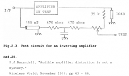
The fact that there is no correlation between these parameters and sound became known more than 70 years ago. At the same time, the first attempts to measure distortions by the compensation method were born. But this required tunable ideal delay lines, which did not exist. The delay lines that were used in sound recording were of a fixed value and were very cumbersome and not suitable for practical use in compensation measurements.
Only Baxandall managed to use a delay of 150 ns in some tests, he did the rest of the delay on
RC-elements.
It is not surprising that, along with professional measuring equipment, self-made vector distortion meters, as well as the SWDT method, have become widely used. But in order to use these methods correctly, it is necessary to clearly understand the ongoing processes in amplifiers.
I have already given an example of the application of the SWDT method by Bob Carver. In Russia, vector distortion meters were widely popularized by I. Akulinichev.
As a result, having no experience in audio engineering, in listening testing, you do not even understand what tests can correlate with sound quality.
You might think that such "Taliban" (in your understanding) as Baxandall, Otala or Hafler did not have professional measuring equipment at their disposal that they began to look for other testing methods other than THD and IMD.
The fact that there is no correlation between these parameters and sound became known more than 70 years ago. At the same time, the first attempts to measure distortions by the compensation method were born. But this required tunable ideal delay lines, which did not exist. The delay lines that were used in sound recording were of a fixed value and were very cumbersome and not suitable for practical use in compensation measurements.
Only Baxandall managed to use a delay of 150 ns in some tests, he did the rest of the delay on
RC-elements.
It is not surprising that, along with professional measuring equipment, self-made vector distortion meters, as well as the SWDT method, have become widely used. But in order to use these methods correctly, it is necessary to clearly understand the ongoing processes in amplifiers.
I have already given an example of the application of the SWDT method by Bob Carver. In Russia, vector distortion meters were widely popularized by I. Akulinichev.
Attachments
The fact that someone has very good measuring equipment does not mean at all that he has the knowledge and experience and ability to think logically about using it.
A monkey remains a monkey, regardless of whether it is with a stick, a grenade, a Kalashnikov assault rifle, or even a sniper rifle.
The method of measuring THD with compensation has been around since long before you and I were born.
I even think it was the first to be used for such a measurement.
But people who use a delay line as compensation must be stupid.
For the simple reason that they do not understand that such delays do not exist in amplifiers.
In amplifiers, the delay (phase rotation) is caused by RC circuits, and thus must be compensated by the same RC circuits.
Also, these people with very mediocre to absent intelligence do not understand that a sine packet at the beginning and end is not a sine at all, and there are harmonics that an audio amplifier cannot reproduce without reducing their amplitude.
But this is not any kind of Speed Distortion, it is simply an amplitude-frequency characteristic.
Testing an amplifier with such a package is equivalent to testing it by feeding it 1MHz-10MHz at the input and crying that an audio amplifier cannot reproduce them without increasing their amplitude.
By suggesting to increase the current of the cascade Vas, you will only reduce its gain, yes, this will increase the linearity, but will reduce the depth of the overall negative feedback...
so that there is no need to increase the current in VAS stage.
Hennady, as you can see, not only did the gain not fall, but on the contrary, it even increased slightly. Here is the loop amplification of various modifications and their DC modes.
Attachments
-
 01_Hafler_DH-120-Mod_Power_Q8.png36.7 KB · Views: 229
 -
 01_Hafler_DH-120-Mod_SCH_current.png17.7 KB · Views: 235
 -
 01_Hafler_DH-120-Sandy_SCH_current.png15.9 KB · Views: 213
 -
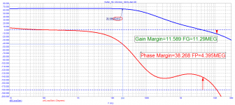 03_Hafler_DH-120-Mod_Loop-Gain_Ku-20kHz.png13.8 KB · Views: 181
 -
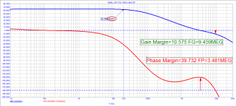 03_Hafler_DH-120-original_Loop-Gain_Ku-20kHz.png14.1 KB · Views: 158
 -
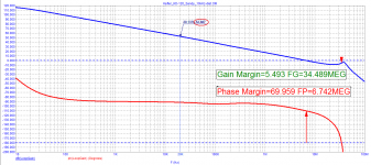 03_Hafler_DH-120-Sandy_Loop-Gain_Ku-20kHz.png14.9 KB · Views: 202
The operation mode of the VAS is not at all clear for the original scheme, there is a variable resistor (trimmer).
There are many things that can be done to improve this scheme, but it won't have so few elements anymore, and it will just become a completely different scheme.
And this scheme is still not bad considering the minimum number of elements.
The art of engineering consists in obtaining maximum effect with minimum costs (elements)
For audiophiles, however, the rule is exactly the opposite, to get the maximum bad result with the maximum amount of elements. 😉 🙂

Sandy, don't stoop to baby talk... the same song is already pretty tired, I think everyoneThe fact that someone has very good measuring equipment does not mean at all that he has the knowledge and experience and ability to think logically about using it.
A monkey remains a monkey, regardless of whether it is with a stick, a grenade, a Kalashnikov assault rifle, or even a sniper rifle.
The method of measuring THD with compensation has been around since long before you and I were born.
I even think it was the first to be used for such a measurement.
But people who use a delay line as compensation must be stupid.
For the simple reason that they do not understand that such delays do not exist in amplifiers.
In amplifiers, the delay (phase rotation) is caused by RC circuits, and thus must be compensated by the same RC circuits.
Also, these people with very mediocre to absent intelligence do not understand that a sine packet at the beginning and end is not a sine at all, and there are harmonics that an audio amplifier cannot reproduce without reducing their amplitude.
But this is not any kind of Speed Distortion, it is simply an amplitude-frequency characteristic.
Testing an amplifier with such a package is equivalent to testing it by feeding it 1MHz-10MHz at the input and crying that an audio amplifier cannot reproduce them without increasing their amplitude.
then it's only good.Hennady, as you can see, not only did the gain not fall, but on the contrary,
Will there be any other modifications to the scheme options?Here is the loop amplification of various modifications and their DC modes.
Where is the truth in the midst of all these disputes?
Where is the best schematic ?
Where is the best schematic ?
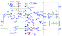
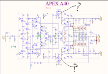
The schematic of the boards that I have. A photo of a completed amp from a member on this forum who is very happy with the amp
I Have plans to build but these disputes have seeded some doubt!
I Have plans to build but these disputes have seeded some doubt!
Attachments

Approval from an amp designer will be appreciated. Even just a "yes it looks like a good design" or "no it has some design issues" could be useful!
or, does Sandy have valid posts?
or, does Sandy have valid posts?
In the pictures above, the schematic is almost the same as the original one. The differences are:
1. Due to bad PSRR of the schematic, there is active filters added in the power supply.
2. The other change is using KSA1381/KSC3504 transistors instead of MJE340/MJE350.
Since I don't found difference in sonic performance from the original schematic. You can also go with the original schematic and PCB. The original single layer PCB allow to use KSA1381/KSC3504 witch are pin compatible with MJE340/MJE350. Active filters could be ommited, or added like e patch on the PCB.
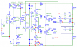
my version of the A40 board
https://www.pcbway.com/project/shareproject/Audio_amplifier_APEX_A40_19c43b0b.html
https://www.pcbway.com/project/shareproject/Audio_amplifier_APEX_A40_19c43b0b.html
Whatever the discussion is, I am carving this in wood right now.The art of engineering consists in obtaining maximum effect with minimum costs (elements)
For audiophiles, however, the rule is exactly the opposite, to get the maximum bad result with the maximum amount of elements. 😉 🙂
Hi everyone,
I have a question for @Joel Wesseling ore everyone who could help me with those pcb's
about the plates for the APEX A40 you have shown. I have seen them and would be interested in them but don't know where I could get them. Alternatively, does anyone have them available in Europe or could they share the gerber files to order such discs and avoid expensive shipping?
I like to build this amplifier on 3 pairs.
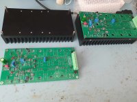
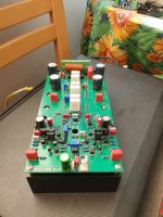
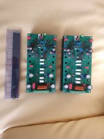
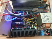
After making the original Apex and that one from post 550 I decide to build one of the Sandy versions of the CFA PA.
Here is the result:
Here is the result:
Attachments
-
CFA_Sandy.pdf638.1 KB · Views: 179
-
 371524888_295299863103388_5550092753443898188_n.jpg244.4 KB · Views: 146
 -
 372276370_243109298716689_8765668663128128051_n.jpg182.4 KB · Views: 157
 -
 375770142_1498823550866508_6692129468328985479_n.jpg221.4 KB · Views: 159
 -
 375758103_1345629119384495_9211778862940942869_n.jpg170.4 KB · Views: 161
 -
 375702604_995800238333798_1452994368060078804_n.jpg191.4 KB · Views: 154
- Home
- Amplifiers
- Solid State
- Apex A40 fundamental improvement. (Sandy)