Thanks for your input @Turbowatch2, I tried to reach something that fits the boundary conditions stated above, but to reach a low enough tuning it needs a much bigger volume of the back chamber. It would work in a BR-enclosure of similar size. Maximum output in kick-bass region would be way lower due to higher excursion without the horn.I want to build a bass bin! My excuse is i need more bass extension for my synergy horns to listen to music. And i thought maybe maybe it could run as a kick in between the synergies and my 15" TH at parties. That is, it is my third project, it absolutely is not necessary to make it as complicated as you are about to witness, but i'd like to figure this out.
Conditions are:
- doesn't need to run terribly low, tuning around 45Hz, as i am many direct neighbours and flatmates.
- should be smaller than the tapped horn. decided to go with about 60/40/30cm
- high efficiency of the horn in the kick region for nice transient response and to be able to use it with the tapped horn (as an experiment at least).
- i already bought a mivoc awm 104, seemed to fit well for that project
[BR with t.box 10-250 VS. VH with mivoc awm 104]
I'll try out some things following @weltersys ideas and @LORDSANSUI input for a more exact sim before making any decisions here.

Hi! Here is the second iteration of my vented horn:

There are two options now. One with a continuously extending horn, and one with two straight section in the beginning to gain a bigger back chamber.
Changes:
A) one extra fold following @weltersys input
B) DN75 pipe as the vent. Not sure where to put it yet; see future ideas below.
C) different expansion profile. The horn starts with a bigger cross section now.
D) more accurate modelling as @weltersys and @LORDSANSUI suggested. (OD with vented rear chamber and 4 PAR segments + better modelling of ground coupling + k-factor for vent length)
There is an optimum between a better horn expansion and bigger back chamber in between these two. I am not sure yet whether to search for that, and/or to give the whole thing a little more Volume.
Ideas:
A) if I give it 5cm more depth, the back chamber could reach 30l. That seems to be what the driver wants.
B) trying to model that the vent is tapping into the horn somehow
C) rounding over the lower knee, as I guess the back segment will resonate badly. (~60cm length -> 205Hz as seen in sim, but also 51Hz qw?)
My biggest question is: When using straight segments in the beginning, am I risking that it starts to honk? Is idea c) going to alleviate that?
And modelling data in the next post again...
Last edited:
[Geometry to pull hornresp inputs from. left: continuous expansion, right: straight sections.]
[hornresp input for the horn with straight sections]
[frequency response of both variants. black: straight section, grey: continuous expansion]
It seems like using straight sections mainly sacrifices sensitivity of the horn. With unchanged outer dimensions and continuous horn expansion, the back chamber volume gets very small, even for the awm 104. That results in a longer and longer BR-port leading to problems fitting it inside. With just 5 cm more depth, I could maybe get a back chamber within the design specs of the driver and a sensitive horn. So that is where i am heading now.
Last edited:
as far as I know monacor do not manufacture drivers themselves.are really Monacor drivers
Late to the party ... maybe I missed it but what exact frequency range do you want to use this speaker? I got the 2 different use cases but how high do you need to run the bass?
The first design is a perfect example of a lot of effort to gain sensitivity in a range you don't need it ... and pretty spikey too. When used as a single woofer you need spl level at low frequencies - and there is no difference between the reflex enclosure and the horn. So just use 2-3 of these chassis (they are not expensive, probably cheaper as the wood when you use birch plywood) in the same volume and do a proper reflex design. Louder at low frequencies and without spikes at high frequencies with a wide bandwidth.
You TH15 looks useable up to 120-130Hz in the simulation. Do yoou have a real measurement? With some absorption material you probably can go even higher? Where do you need your crossover to your top?
Your new designs - the one with the straight sectioin isn't a horn - it's a pipe and simply shows a resonance. (you always have a mixture of pipe resonances and some gain of some horn sections in such constructions). Construction over all looks better as the first attempt!
But you have to ask - WHERE do you need your SPL? At 90Hz narrow band? If you don't gain significant sensitivity in the frequency area you NEED it (that would be low frequencies around 60Hz for playing alone) it's wasted space and wood and strength when you need to carry it ;-).
If you really need a filler Horn from 80-180Hz something like the HD15 is a good attempt. Build 2 of them and you could use it with plenty of EQ at low frequencies in your living room.
Most mixed Reflex/Horn constructions need a lot of volume and are not louder as 2 drivers in the same volume.
Thank you for your thoughts! Quick question, will think it through properly later: do bandpass horns like the hd15 have a good transient behavior as horns have?
The best. Directly after a closed speaker. It's more or less a closed speaker with a horn in front to add some sensitivity. And it's a proper horn with no resonances in the area you use it. Measurements show that there is just a little bandpass effect, so no problem with impuls responses here.
For your usecase - you could also just use 2-4 chassis in a closed volume! EQ the low frequencies for home use (which is easy in a closed volume) and have a great SPL/volume ratio at higher frequencies. Not very common but works well.
Just imagine a HD15. The Backvolume is really small. You could easily fit 2 15" in the same volume as the whole HD15. Let's asume we have enough amp power to drive 2 drivers instead of one ... you have +6dB SPL at 60Hz and maybe 3dB less at 150Hz. You could let it run up to 300Hz with the right drivers or even higher. You save time in building the cabinet but have to buy 2 drivers.
This would be the best sounding sollution for you:
It is from Volvotreter. You can scale it down for 12" or 10" driver.

It is from Volvotreter. You can scale it down for 12" or 10" driver.
In #9 I had suggested the extra fold using parabloic expansion, not straight sided top and bottomA) one extra fold following @weltersys input
Sounds a little small for the excursion of your driver, check the port velocity.B) DN75 pipe as the vent. Not sure where to put it yet; see future ideas below.
The last section of the horn expansion does very little, using that volume for the chamber will make the chamber volume bigger, something like this:A) if I give it 5cm more depth, the back chamber could reach 30l. That seems to be what the driver wants.
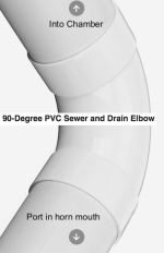
Using a 90 degree elbow would allow you to twist off the port in the horn mouth section used for the lower 30-40Hz Fb home use tuning, the shorter section for a 50-60Hz Fb to fill in below the horn cutoff. Three different Fb (internal port only, internal with elbow, elbow and final section) can be achieved within seconds.
With the distance from the horn sidewalls being many times the diameter of the port, probably not much effect on the position of the port exit.B) trying to model that the vent is tapping into the horn somehow
Rounding over, or putting a 45 degree reflector in the lower knee would smooth some of the "honk", but reduce horn volume a bit.C) rounding over the lower knee, as I guess the back segment will resonate badly. (~60cm length -> 205Hz as seen in sim, but also 51Hz qw?)
My biggest question is: When using straight segments in the beginning, am I risking that it starts to honk? Is idea c) going to alleviate that?
Expanding, rather than straight sections will honk less.
Attachments
more accurate modelling as @weltersys and @LORDSANSUI suggested. (OD with vented rear chamber and 4 PAR segments + better modelling of ground coupling + k-factor for vent length)
If you model it as OD it will not be accurate because the end of the vent if placed inside the horn, in this case you need to model as Tapped Horn (TH) with vented rear chamber.
Late to the party ... maybe I missed it but what exact frequency range do you want to use this speaker? I got the 2 different use cases but how high do you need to run the bass?
The first design is a perfect example of a lot of effort to gain sensitivity in a range you don't need it ... and pretty spikey too. When used as a single woofer you need spl level at low frequencies - and there is no difference between the reflex enclosure and the horn. So just use 2-3 of these chassis (they are not expensive, probably cheaper as the wood when you use birch plywood) in the same volume and do a proper reflex design. Louder at low frequencies and without spikes at high frequencies with a wide bandwidth.
You TH15 looks useable up to 120-130Hz in the simulation. Do yoou have a real measurement? With some absorption material you probably can go even higher? Where do you need your crossover to your top?
Your new designs - the one with the straight sectioin isn't a horn - it's a pipe and simply shows a resonance. (you always have a mixture of pipe resonances and some gain of some horn sections in such constructions). Construction over all looks better as the first attempt!
But you have to ask - WHERE do you need your SPL? At 90Hz narrow band? If you don't gain significant sensitivity in the frequency area you NEED it (that would be low frequencies around 60Hz for playing alone) it's wasted space and wood and strength when you need to carry it ;-).
If you really need a filler Horn from 80-180Hz something like the HD15 is a good attempt. Build 2 of them and you could use it with plenty of EQ at low frequencies in your living room.
Most mixed Reflex/Horn constructions need a lot of volume and are not louder as 2 drivers in the same volume.
Hi! To cut complexity down a little, I will try to make it fit the synergies in my room first.
From experience i can say the TH comfortably plays to 120Hz without EQing out of band resonances. Unfortunately I have no real measurements, I only measured it when aligning it before parties. Next time I'll try to do a near field measurement.
Last party, I positioned it in a center position in a 5-6m wide room and it let it play from 40-120Hz. Sounded tight and punchy. The relatively high low-cut (normal low-cut = 32Hz; 24db/oct.) reduced noise pollution quite a bit, so it actually plays a bit below that.
So, actually no kickbin needed for my purpose and i accept that the double use is too complex for me at the moment.
I'll post new versions in a following post. I went down the bandpas horn route now as well. 🙂
Well, that's a consequent but humongous design. I like that approach, but I am affraid I have to allow for more compromises in my design. A sub in your livingroom with a depth of 1m and 350l is really a statement!This would be the best sounding sollution for you:
It is from Volvotreter. You can scale it down for 12" or 10" driver.
View attachment 1237680
Yes, I got that. Introduced that, in an attempt to simplify construction and bring down the peak in frequency response without realising, that I am starting to exchange the horn for a pipe.In #9 I had suggested the extra fold using parabloic expansion, not straight sided top and bottom
I am hesitant to put the extension pipes on the front side of the enclosure, because of the looks. Put i have an idea for that, see the newest Versions below:
Thank's a lot for your effort with the drawings!!!
First of all: Thank you for your ideas and input!
I tried to follow your advices and tried a few things in Version 3 of the design:
A) following @weltersys drawing more closely, but sticking the port through the horn to the back
B) A bandpass horn as @IamJF suggested, but with a vented back chamber
C) FLH to see if i can get the horn response low enough
D) Making a sealed or BR-enclosure is not abandoned, but no fun to figure out. So that's my exit strategy if nothing works

findings for each variant are:
A) The ported chamber works very well, even with a bigger pipe (DN110), but I still fall into the trap of generating a lot of sensitivity in the wrong place. I can tune the horn lower with bigger cross sections in the beginning, but then it's a pipe again and might sound bad. :-/
B) Bandpass-horn I tunable to the right place, but falls off rapidly outside the passband. So what i did here seems to be a real bandpass and not something like the HD15 with a negligible bandpass effect?
C) would be stupidly easy to build, but just doesn't play low enough and spikey because of the small mouth.
Sooo, still work in progress here. again, hornresp in the next post
I tried to follow your advices and tried a few things in Version 3 of the design:
A) following @weltersys drawing more closely, but sticking the port through the horn to the back
B) A bandpass horn as @IamJF suggested, but with a vented back chamber
C) FLH to see if i can get the horn response low enough
D) Making a sealed or BR-enclosure is not abandoned, but no fun to figure out. So that's my exit strategy if nothing works
findings for each variant are:
A) The ported chamber works very well, even with a bigger pipe (DN110), but I still fall into the trap of generating a lot of sensitivity in the wrong place. I can tune the horn lower with bigger cross sections in the beginning, but then it's a pipe again and might sound bad. :-/
B) Bandpass-horn I tunable to the right place, but falls off rapidly outside the passband. So what i did here seems to be a real bandpass and not something like the HD15 with a negligible bandpass effect?
C) would be stupidly easy to build, but just doesn't play low enough and spikey because of the small mouth.
Sooo, still work in progress here. again, hornresp in the next post
[variant A, vented horn]
[variant B, vented bph]
[variant C, flh]
Options seem to be the bph or making the vented horn be more similar to a pipe...
For people that are out of the loop, this is what I'd do with the bandpasshorn. The idea is to kind of optimise the enclosure for transient response in the kick bass region and EQ it down to being flat:
Last edited:
First - I would never suggest a bandpass horn with reflex! 😎
Construction B is a double vented Bandpass with fancy port if you ask me. When you have to tame a 8dB resonance with EQ ... the design is NOT optimised for transient response! This rings. You would need a wideband & flat response for transients. With low Q orders of fall off - no ports.
Interesting that variant C is not going deeper? How long is the hornpath? Can you testwise try to make the mouth bigger? It should work better ... at least with stacking.
Interesting that variant C is not going deeper? How long is the hornpath? Can you testwise try to make the mouth bigger? It should work better ... at least with stacking.
Horn length minus driver entry position is 128cm. If I model it with only two parabolic segments, the fundamental frequency is a little lower.
Thanks, so what I did is not at all what you suggested. 🙂 I will not go down the bandpass route for now, as i don't think i can make it work. I have a limited understanding of horns, but even less of an idea of bandpass constructions...First - I would never suggest a bandpass horn with reflex! 😎
Construction B is a double vented Bandpass with fancy port if you ask me. When you have to tame a 8dB resonance with EQ ... the design is NOT optimised for transient response! This rings. You would need a wideband & flat response for transients. With low Q orders of fall off - no ports.
So next steps for now are:
- trying to find a good compromise for a pipe'ish horn for Variant A
- checking out other cheap second hand drivers in Variant A
Or there is the uninspiring but economic solution D.
Get a bunch of 15" Reflex woofers and ditch the rest. They play high, they play low enough, they can play tight and you can scale them easily and transport them easily. You can do every job with them.
Use a chassis from one of the bigger companies so you can still buy it in 10 years and expand your setup. Try to buy directly from a distributor for a good price, B&C in Germany is great!
Then use the time for planing and building the horn for doing jobs ;-)
The cost of the wood would probably buy a 2nd speaker ...
I know that's not fun but that's what a sane PA bussines would do.
But that's also the nice thing with diyAudio - nobody forces us to be sane 😎
this is the word in PA world. I had a friend who made 8 x 12" BP6 subs. 40-125 Hz, when he was on small things 2 subs + small tops. On larger ones he used all 8 of them.scale
- Home
- Loudspeakers
- Subwoofers
- "small" vented horn project