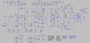
@jcalvarez,
Tempted to try your suggestion to remove the coupling cap to the LTP again, but with my CCS rather than the 10M45, as that’s one combination I haven’t tried yet. Any experience with a CCS other than the 10M45/90?
Tempted to try your suggestion to remove the coupling cap to the LTP again, but with my CCS rather than the 10M45, as that’s one combination I haven’t tried yet. Any experience with a CCS other than the 10M45/90?
I use current regulator diodes from the 1N5299 ... 1N5314 family. 1N5312 and 1N5313 parallel to set 3.9mA+4.3mA=8.2mA for the LTP. There are better CCS out there, but I chose it for simplicity.
I have only used 10M45S with tubes, but no reason why another CCS wouldn't do well. 10M45S is just simple, 1 transistor plys two resistors, no need for reference supply etc.@jcalvarez,
Tempted to try your suggestion to remove the coupling cap to the LTP again, but with my CCS rather than the 10M45, as that’s one combination I haven’t tried yet. Any experience with a CCS other than the 10M45/90?
There are still two dangers from this model. First is that the output valves' loadline is normally quite different with actual (reactive, etc.) speaker loads than with idealized resistor loads, so output stage distortion has components at different levels, timing and frequency distribution in real world than with resistor load model. So, distortion cancellation doesn't work the same way in real world.So I was looking at the KT88 output on its own and comparing it with the ECC88 followed by the LTP. In all cases the distortion of the two stage together is much lower than that of just the output stage. So yes distortion cancellation occurs.
Second, and I think maybe more insidious, is that testing is only being done at full output power. In the semi-con amplifier world the term "transconductance doubling" is used to refer to operation within the Class A region, and transfer in and out of this region is never without some distortion issues. In the normally much hotter vacuum valve world, we would look at this from the other (and actually much more realistic) end of the stick, and say that "transconductance halving" occurs beyond the Class A region.
All important musical information happens in the Class A region, peaks beyond this region are rare (in hot valve amplifiers), and errors there, like distortion, are hard to hear, clouded by speaker distortion, and much less important to our own hearing mechanisms. Our design judgments should be biased towards best performance within the Class A region, with only passing notice taken of peak output performance. To focus on peak output at the expense of the musical output range sacrifices real world performance for a number on paper, which is not even real with speaker loading. Our common assumption of monotonicity is false - the age-old tests at full power are not only almost meaningless, but can become false gods, leading us astray.
All good fortune,
Chris
@Chris Hornbeck,
Your long winded reply misses two things that are glaringly obvious, which, at least to me, shows you’re only making these posts to address the things you believe are happening, but which are actually not.
1) If you look at the measurement plots I posted you’ll notice I post THD vs. power, on a scale from 1 to 100W. Also the THD vs. frequency plot is at 10W. So at no point have I ever ‘just’ measured the performance at full output power.
2) I’m not interested in pure class A behavior, if that was the case I’d have operated the KT88 in triode mode.
So when you speak of assumption you’re right, but you’re the one making the assumptions. Thank you.
I'm only suggesting that we zoom out, rather than zoom in. Design choices begin with defining goals, and making assumptions. I'm proposing that the optimum design choices for best musical performance can conflict with optimum design choices for best distortion numbers at full power into resistive loads. No need to bristle, just a technical discussion among interested colleagues.
All good fortune,
Chris
All good fortune,
Chris
There’s no technical discussion if you don’t offer technical feedback, and no, merely making long winded statements doesn’t count as such, at the very least ‘we’ would like to see a little bit of math, perhaps even een hand drawn schematic with a novel approach. And yes, I’m being a bit bristle as you’re not in the least bit being helpful or constructive. Thank you.
Please forgive me if I've offended you. Your thread, your circus, your monkeys.
All good fortune,
Chris
All good fortune,
Chris
You’re welcome to join the party, but please offer some constructive feedback. Drinks are on the house! Thank you.
Last edited:
The best pentode is a triode 🙂Toying with this, a 'BestPentode'
Never tried that, all I can see is that Q3 collector-base junction will be conducing when the plate goes lower than the base voltage, connecting C19, R27 and R42 to the plate.
May we see that by this time next year? I'm 91 yrs olde now, I may not live to marvel at that,😀if that was the case I’d have operated the KT88 in triode mode.
@jhstewart9,
Don’t worry! I was actually planning on getting this finished before the end of the year. I just want to evaluate a few more options, and I could probably use some assistance with that.
For example I have a number of D3a pentodes I want to try as well, but am unsure what a good biasing point would be, and can’t seem to find any examples, so I’ll need to do a bit of homework to get that figured out.
jhstewart9,
Keep going, we need you.
Keep going, we need you.
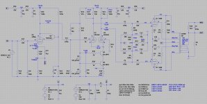
Alright, quick update. I've built up two new prototypes from scratch so I could actually listen to the amplifiers in stereo and made a few small modifications:
1) 6N1P-EV rather than a 6922 for the LTP.
2) Feedback network reworked.
3) Coupling cap size optimized to mitigate low freq. oscillation.
Performance is slightly better with the 6N1P-EV and I have run out of ideas to further optimize the design, so I think this is the final schematic.
Proto 068

1) 6N1P-EV rather than a 6922 for the LTP.
2) Feedback network reworked.
3) Coupling cap size optimized to mitigate low freq. oscillation.
Performance is slightly better with the 6N1P-EV and I have run out of ideas to further optimize the design, so I think this is the final schematic.
Proto 068

- Home
- Amplifiers
- Tubes / Valves
- KT88 PP - Dotting the Is, crossing the Ts
