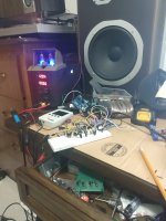
I desinged this amp while locked up in colony farm. I really want to make it better as the test I ran on it showed great sound until the mossfets I was using over heated.
I have no idea about getting impedence right or any of that fancy math ****. I saw a diagram for a A/B class amp built one and it sounded like **** and quickly cooked out my PNPs.
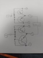
So i took the circuit and a TL082 opamp to invert one side and give noninverted the same gain and ripped some fets out of some scrap electronics.
I got a great sounding amp for the first song by the end it was overheating and my fets where going into thermal runaway.
I have also fed this circuit a fixed frequency and used it as an inverter to create AC voltage out of my dc power supply.
What id like to do is somehow get some feedback resistors to the output. (Im thinking i can slow down how fast the output voltage picks up and get a more analog like sound out of it)

I have no idea about getting impedence right or any of that fancy math ****. I saw a diagram for a A/B class amp built one and it sounded like **** and quickly cooked out my PNPs.
So i took the circuit and a TL082 opamp to invert one side and give noninverted the same gain and ripped some fets out of some scrap electronics.
I got a great sounding amp for the first song by the end it was overheating and my fets where going into thermal runaway.
I have also fed this circuit a fixed frequency and used it as an inverter to create AC voltage out of my dc power supply.
What id like to do is somehow get some feedback resistors to the output. (Im thinking i can slow down how fast the output voltage picks up and get a more analog like sound out of it)
Last edited by a moderator:
i got the diodes backwards sorry I got this circuit on a breadboard right now using parallel bipolar transistors and its working fine got some crackle
Theres very little information here about how you've built this.
So not much for anyone to go on to try and help you.
I'm by no means an amplifier designer in even the simplest of worlds.
But.
mosfets have very wide bandwidth (ten or hundreds of MHz) and if not limited or controlled, you will indeed get high frequency runaway causing burnout.
You'd need to use capacitors across them to limit their response.
All I can suggest is look at some of the other mosfet designs here to see how they've controlled this.
You might also need to look into trace routing and heatsink sizing.

Aren't your diodes sorta shorted by their connection to C1 and C2? Backward or not...
Let's say the two outputs did setup to +V/2 and -V/2 at idle. You'd still need coupling caps to connect them to a speaker.
I'd think you'd be better off running each section from the + supply only, rather than have a separate - supply for the "lower" half.
When designing with discrete components, something like LTSpice is your friend.
You need emitter resistors and the bias needs to be adjustable, ie a VBE multiplier vs a pair of diodes. The 0V supply connection in the middle is wrong. Both NPN connect to V+ and both PNP connect to V- and the speaker (only) returns to the supply 0V. I hope you are using LARGE transistors, ie to220 or to247 types, mounted on a large heat sink. The supply voltage is important and should be no more than the VAS voltage.
I'd say you are a long way from designing a reliable amplifier. I would suggest you play with cheap amplifier boards from Amazon and when you completely understand them and can improve them, then you can design an amp from scratch. That will take a few years of experience and study. There is a lot of math involved, but you can cheat by using spice simulations, bearing in mind that virtual transistors don't blow up when you abuse them like the real thing do.
Take every opportunity to reverse engineer other people's work. High school and 1st year college courses are not enough. Even engineers with a 4-year degree regularly fail at designing amplifiers. You need to invest years into the subject.
Ya i messed up on the diodes and my input. Im doing this from memory the signal goes to center of diodes and there is no connection between gates also diodes are backwards.
Also I do have this hooked up on a breadbord and im listening to ramstein on it as I type this
Also I do have this hooked up on a breadbord and im listening to ramstein on it as I type this
They are. One could feed the input signal to the centre point between the two diodes. Add emitter resistors.Aren't your diodes sorta shorted by their connection to C1 and C2? Backward or not...
The design will work. The bias of the output pair won't be optimal but if you wrap an opamp around it you should be able to get pretty good performance.
Tom
Here's the circuit fixed. By wrap a opamp around it do you mean the input opamp and get my bias voltage from output? Can I do that? I'm using a tube preapm into this circuit right now and running a 4 ohm 5w rca speaker and it's not horrible I've had Bluetooth speakers sound much worse before.

To where are the two input signals referenced, power supply ground?
If so, is the 0V "output" also connected to the power supply ground?
What does your drive circuit (if any) look like, since this circuit has no voltage gain?
If so, is the 0V "output" also connected to the power supply ground?
What does your drive circuit (if any) look like, since this circuit has no voltage gain?
Last edited:
That looks much more reasonable than the original. Wrap input op-amp feedback loop around output of each transistor pair to get feedback. Biasing may be sub-optimal but gets generally in the right area for BJTs.
For MOSFETs you would want a larger voltage drop between the gates and likely a resistor at each MOSFET gate.
A few details omitted that are possibly relevant to the issues you experienced: what Transistors are you using? Looks like no heatsinks, is that correct? What are your voltage rails and signal levels?
Yes, when adding the heat sinks, use isolation pads and thermal paste,
unless the power transistors are fully insulated and have no metal tabs.
unless the power transistors are fully insulated and have no metal tabs.
H
HAYK
Your circuit is functional even without input capacitors. Your problem of over heat are the diodes. Either buy diodes that can be mounted upon the transistors or use any transistor that can. You need to tie the bases to the collectors and they become diodes.
If you have silicon glue you can glue the actual diodes.
If the power is not high, try this.

If you have silicon glue you can glue the actual diodes.
If the power is not high, try this.
Last edited by a moderator:
I really don't know what I'm doing here I came up with this by not understanding the proper power supply of a AB amp and I guess fixed it by making something that already exists.
I'm currently using two 2n222s in parallel for each npn and using the pnp equivalent the same way. It works but I'm going to drive it with a opamp before the opamp that inverts the signal to control my gain. I'm currently using a tube preamp I built from a kit for that.
- Home
- Amplifiers
- Solid State
- Amp I designed in the mental hospital, help me make it better