Hi!
I want to build a bass bin! My excuse is i need more bass extension for my synergy horns to listen to music. And i thought maybe maybe it could run as a kick in between the synergies and my 15" TH at parties. That is, it is my third project, it absolutely is not necessary to make it as complicated as you are about to witness, but i'd like to figure this out.
Conditions are:
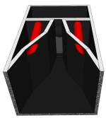
This is what i came up with:


The port is oriented like that to be able to reach the driver from the top plate.
What i am unsure about is:
i'll put my simulations in the next post.
I want to build a bass bin! My excuse is i need more bass extension for my synergy horns to listen to music. And i thought maybe maybe it could run as a kick in between the synergies and my 15" TH at parties. That is, it is my third project, it absolutely is not necessary to make it as complicated as you are about to witness, but i'd like to figure this out.
Conditions are:
- doesn't need to run terribly low, tuning around 45Hz, as i am many direct neighbours and flatmates.
- should be smaller than the tapped horn. decided to go with about 60/40/30cm
- high efficiency of the horn in the kick region for nice transient response and to be able to use it with the tapped horn (as an experiment at least).
- i already bought a mivoc awm 104, seemed to fit well for that project
This is what i came up with:
The port is oriented like that to be able to reach the driver from the top plate.
What i am unsure about is:
- is this how you take the ground extension of the horn path into account?
- how to make sure the BR-port is tuned correctly with the expansion at the end and the kink at the inside.
- am i an idiot? 😉
i'll put my simulations in the next post.

Hornresp input:


and the results in comparison with a simple BR-bin

and how i imagine it in my room with eq. I will see about crossover frequency, but you get the idea.

So, what do you think? Are there obvious mistakes? Someone already tried the same and failed? 🙂
and the results in comparison with a simple BR-bin
and how i imagine it in my room with eq. I will see about crossover frequency, but you get the idea.
So, what do you think? Are there obvious mistakes? Someone already tried the same and failed? 🙂
It would help to know what tapped horn you plan to use the kick bin with, the phase shift at the bottom of its response due to the porting ("phase inversion") will make phase alignment difficult.
- high efficiency of the horn in the kick region for nice transient response and to be able to use it with the tapped horn (as an experiment at least).
- i already bought a mivoc awm 104, seemed to fit well for that project
- is this how you take the ground extension of the horn path into account?
- how to make sure the BR-port is tuned correctly with the expansion at the end and the kink at the inside.
- am i an idiot? 😉
The Mivoc AWM 104 does not look like the best kick bin driver, but it's what you have..
Might be better to reduce the back chamber volume and increase path length to extend response lower with a sealed bin, or shorten the port to get more output in the 60-80Hz range.
The ground extends beyond the horn path, but the sides of the horn end at the cabinet front, so your S2-S3 is estimated a bit longer than what your box shows.
The sides of the cabinet are parallel, so expansion is "par", not "exp". Using another horn segment (S3-S4) to approximate the lower/last part of the horn would be a little more accurate.
Not sure what constitutes "correct tuning" in your design, but I think the port ends about like this:
The end of the port inside the cabinet is relatively close to the cabinet wall, which makes the length more ambiguous, could be somewhere between what you drew and the above.
That said, Hornresp assumes a round horn path, and your port has a high aspect ratio by comparison.
Over about a 6/1 aspect ratio air frictional losses reduce the effective port diameter, lowering Fb, and increasing port velocity.
Hi!
Main use will be in my room, using it as a kick bin with the tapped horn is more of an experiment. The idea was to crossover to the tapped horn before the port actually does anything. it will only be there for low end extension when i am listening at lower levels in my room. Anyway, the Tapped horn is called lonely.TH15 and is designed for the super cheap 15lb075 driver by Viktor who is on German forums. (my build thread: https://www.lautsprecherforum.eu/viewtopic.php?p=112265#p112265 and the original thread https://www.lautsprecherforum.eu/viewtopic.php?f=55&t=8760). Simulation of it:

Though process to use exponential was: I figured out how big the mouth and path length would be, then exported the exponential horn profile and followed the resulting cross sections at the fold and kinks to approximate the exponential expansion rate. Is that approximation too rough?
With correct tuning i meant that the simulated port dimensions are actually what is going to be build. Maybe i should adjust its cross section, to avoid the kink in it.
Main use will be in my room, using it as a kick bin with the tapped horn is more of an experiment. The idea was to crossover to the tapped horn before the port actually does anything. it will only be there for low end extension when i am listening at lower levels in my room. Anyway, the Tapped horn is called lonely.TH15 and is designed for the super cheap 15lb075 driver by Viktor who is on German forums. (my build thread: https://www.lautsprecherforum.eu/viewtopic.php?p=112265#p112265 and the original thread https://www.lautsprecherforum.eu/viewtopic.php?f=55&t=8760). Simulation of it:
Though process to use exponential was: I figured out how big the mouth and path length would be, then exported the exponential horn profile and followed the resulting cross sections at the fold and kinks to approximate the exponential expansion rate. Is that approximation too rough?
With correct tuning i meant that the simulated port dimensions are actually what is going to be build. Maybe i should adjust its cross section, to avoid the kink in it.
Last edited:
And this is what I'll approximately get with an extra fold at the top, smaller chamber size and a much smaller port, as it wouldn't fit any more as it was.
In reference to the path length: I saw that @LORDSANSUI kind of did it like that in his plans and I just went with it. (https://freeloudspeakerplan.rf.gd/)
Is he refering to large stacks with the path length in his models, where the boundaries on the sides would be given by coupling of the mouths, maybe? Or do I simply get something completely wrong here.
Is he refering to large stacks with the path length in his models, where the boundaries on the sides would be given by coupling of the mouths, maybe? Or do I simply get something completely wrong here.
looks fun.
port tuning would seem to be very very low
as shown in drawing.
would assume 3 shared walls end correction
closer to 2.1 to 2.3 not .732
So would be much shorter.
port tuning would seem to be very very low
as shown in drawing.
would assume 3 shared walls end correction
closer to 2.1 to 2.3 not .732
So would be much shorter.
Looking to the light blue line it doesn't looks you are using the advanced center line methodology to define the horn length properly.
Besides the driver you are planning to use could be very different from the ones used in the past with Martin Audio boxes WMX, WLX and WSM they are a very good place to start as benchmarking for you DIY solution.
What you are proposing is interesting, the vent looks very long, probably because you want to reach to 45Hz and increasing vent length is the easiest way to reach there, but once this design is a compound box, the final result is a combination between front and back horn (vent), so you need to check if your driver is the best option for this design. As weltersys said, you may need to change the tunning frequency or at least to be carefull with the tunning.
Remember to check Particle Velocity for the chamber vent and also Group delay.
Skran is also a similar design (compound) well documented from Ricci that can be used as benchmark too.
https://data-bass.ipbhost.com/topic/742-riccis-skram-subwoofer-files/
MHB and MPH, also have some documentation available in the web, so you can collect more data from them. They will not used the same driver as you and maybe nether they have the same output you need, but if will speed up your learn curve to figure out the best way to tunning this particular box design for you case increasing your confidence level.
Main use will be in my room, using it as a kick bin with the tapped horn is more of an experiment. The idea was to crossover to the tapped horn before the port actually does anything. it will only be there for low end extension when i am listening at lower levels in my room.
With correct tuning i meant that the simulated port dimensions are actually what is going to be build. Maybe i should adjust its cross section, to avoid the kink in it.
I'd suggest using the extra path length for lower horn response, also makes mounting the driver way easier,
something like this for the first part of the horn on the top (not to scale);
Using plumbing fixtures for the ports makes it easy to switch between different tunings.
I'm actually using a pair of 8" tuned to 35Hz for my subs in my office. When used for PA, can switch the tuning anywhere from 76Hz on down depending on whether they are used alone or with subs.
https://www.diyaudio.com/community/threads/hot-rod-8-2-way-pa-studio-monitor.343215/
Your 10" has a lot more excursion, something around 100mm diameter or more would get the port velocity down.
looks fun.
port tuning would seem to be very very low
as shown in drawing.
would assume 3 shared walls end correction
closer to 2.1 to 2.3 not .732
So would be much shorter.
Thanks! I will look deeper into that to get the simulation right here. Does the virtual, additional length of the port subtract from the rear chamber volume? I guess it should, as the air is resonating and not acting as a spring in that region?!
I will definitely prepare for corrections of the port area or length. Either as @weltersys suggested below, or via extra panels somehow.
Looking to the light blue line it doesn't looks you are using the advanced center line methodology to define the horn length properly.
Besides the driver you are planning to use could be very different from the ones used in the past with Martin Audio boxes WMX, WLX and WSM they are a very good place to start as benchmarking for you DIY solution.
What you are proposing is interesting, the vent looks very long, probably because you want to reach to 45Hz and increasing vent length is the easiest way to reach there, but once this design is a compound box, the final result is a combination between front and back horn (vent), so you need to check if your driver is the best option for this design. As weltersys said, you may need to change the tunning frequency or at least to be carefull with the tunning.
Remember to check Particle Velocity for the chamber vent and also Group delay.
Skran is also a similar design (compound) well documented from Ricci that can be used as benchmark too.
https://data-bass.ipbhost.com/topic/742-riccis-skram-subwoofer-files/
MHB and MPH, also have some documentation available in the web, so you can collect more data from them. They will not used the same driver as you and maybe nether they have the same output you need, but if will speed up your learn curve to figure out the best way to tunning this particular box design for you case increasing your confidence level.
The reasoning behind the driver was: it's meant to be in small BR-enclosures, so why not take that and attach a horn in front of the driver. I'll try to make it work, as i have it now. Worst case is, that it doesn't work and i learned a lot. 🙂
I'll check out out the skram and look into how the advanced centerline is actually derived from the geometry. Thanks a lot for the input!
I'd suggest using the extra path length for lower horn response, also makes mounting the driver way easier,
something like this for the first part of the horn on the top (not to scale);
View attachment 1229220
Using plumbing fixtures for the ports makes it easy to switch between different tunings.
I'm actually using a pair of 8" tuned to 35Hz for my subs in my office. When used for PA, can switch the tuning anywhere from 76Hz on down depending on whether they are used alone or with subs.
https://www.diyaudio.com/community/threads/hot-rod-8-2-way-pa-studio-monitor.343215/
Your 10" has a lot more excursion, something around 100mm diameter or more would get the port velocity down.
Nice, of course, that's so much better in every regard to put an extra fold there!
And i really like the DIY mentality of your external ports! I'd have to stick them through the horn, or have them at the front/sides, though. I'll try some things out in CAD. Would it be problematic to have the port-exits somewhere in the horn itself? I mean, when the ports resonate, the air in the horn should move freely and as soon as the horn loads, the ports act as if they were closed, right?
Last edited:
The port response extends above tuning, you can look at their response in Hornresp.
I don't think the location of the port ends will make much difference to the response.
I don't think the location of the port ends will make much difference to the response.
Would it be problematic to have the port-exits somewhere in the horn itself?
Problematic not, but it maters a lot, if you do this you need to change the way you model the loudspeaker. It will not be Nd anymore and you may need to change it to TH (Tapped Horn) with others adjustments. Check attached image as an example.
While, if you change the placement of the port-end inside the chamber you can keep the model as it's and you can check the effect trough unmasked SPL response.
Simulation is the way to go to check if the impact is minimal or meaningful.
Attachments
The driver is a heavy cone, medium soft suspension, medium strong motor, specialized HIFI design. Very good for a small vented or a small, closed high pass cabinet, neither used higher than 200Hz.
Exactly the opposite to a dynamic kick driver. Some here may not have realized this.
I don't know what you want to learn from using the wrong driver for the wrong task? Masochism? There are many low cost driver that perfectly fit the bill for your needs.
If you just want to waste time and money, a good project. For most of us building a well made cabinet is more expensive than the driver in it. Not well made cabinets will not show the correct result of a concept...
Of course I don't want to build something, that doesn't work!
The other comments sounded more like it is not an ideal driver instead of a completely wrong choice, as you state it. So i read from your comment that the idea of a small BR-cabinet with an extra horn in front is not doable with said driver?
Crossover would be under 200Hz and with @weltersys input I'll try to get the horn down to ~80Hz. (regardless of using the mivoc awm 104 or another driver).
What are the simulations not showing in regard of a bad driver choice? Muddy sound i guess?
Last edited:
The AW104 is a driver with an extra heavy cone. It needs time to get moving and once in motion, some cycles to come to a stop. Such special drivers, when suspension and drive are carefully adjusted, can reproduce low frequency from small volume. They are best cut off around 80Hz.
Your projected kick driver should start where the MIVOC is x-ed over. A driver that follows a fast impulse instandly. Usually a strong, but not overly heavy cone, a hard suspension and a strong drive. Quite the opposite to the AW104.
There is noting clever in "einfach mal ausprobieren, vielleicht gehts ja doch" (just try it, maybe it works) if you, others, the manufacturer and physics tell you "it will not work". Go have a look at the Thomann drivers, they are high value and could be used in your application.
https://www.thomann.de/de/the_box_speaker_102508a.htm could be a candidate.
The Mivoc AW104 is a very good, well known chassis, sell them on eBay and you should get enough to buy a well suited driver.
Last edited:
Although I also did say the Mivoc AWM 104 does not look like the best kick bin driver, (but it's what you have..), it will be better than a dedicated low mid driver for the dual usage you plan, the main use being in your (home) room where extended LF rather than articulate mid range will be more useful.
If you read from the beginning, he wants something between his 15" TH and his top. So the shown THOMANN driver should fit.
As he lives in Germany, there is no shortage of drivers, so no need to stick to the ones he has and spend lots of money for non working cabinet building around the MIVOC.
https://www.lautsprechershop.de/pdf/mivoc/awm104.pdf
The AW104 is a great driver, reaching 30Hz in a 35 liter vented enclosure, with a dry, musical sound, but, sorry, no way a mid horn driver!
I think the thread starter has been given enough information to draw his own conclusions now.
- Home
- Loudspeakers
- Subwoofers
- "small" vented horn project