if I understood it correctly… yes.^ ".. reverse the speaker polarity..."
My mosfet version of this amp has positive 2nd and I reverse the speaker terminals to get it negative.
Correct, using the definitions we've borrowed from Nelson.^ ".. reverse the speaker polarity..."
Huh? The phase of the 2nd order harmonic, positive or negative, is relative to the fundamental.
If you "swap the speaker cable", the relative phase of the distortion to the fundamental inverts. See H2 article. (To me) the easiest way to stop the head from swirling with the concept is to literally turn the page upside down as Nelson suggests. Otherwise you can conceptualize / visualize that since the H2 is literally at 2x the frequency of the fundamental.; there is one positive going and one negative going distortion peak for each fundamental peak. So, every other peak will be 'positive or negative' aligned. Since we define the relative phase of the distortion to the positive going waveform in the fundamental... it flips when you flip the entire signal.if you reverse the polarity, you are reversing both the distortion elements AND the fundamental. Huh?
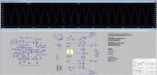
Another Visualization Example - Hopefully the format will stick. Not totally precise... but for a 30s mash up... hopefully it illustrates the idea. The red font defines the relative distortion to the positive going half of the fundamental.
When you get your scope and other toys, you can check it out. It's super neato. In the interim... just swap cables back and forth and see what you dig. 🙂
Have fun!!!!
As always... I may have this completely ***-backwards, but it's the way I noodle through it.
Is CRC not a "must"?
evidently not
simple as - if you can without "R", don't use it
if not, use it
^ Definitely.
If someone's feeling totally geeky they may even use a spreadsheet and a few formulae to see how the distortion affects the voltage at the speaker.
I'm sure there are better tools, but... you use what you have.
Is it silly, yes. Is it illustrative of the effect... for when the speaker is "sucking or blowing" at a fundamental frequency whether the distortion is "adding blow or suck" and the relative timing .... also yes.
Does it mean I understand it... definitely not!
If one has the AlephJ clone around, test it with that amp. All my first watts react to it, but AJ can go from non interesting to very interesting with the flip. Maybe its just my ears...Correct, using the definitions we've borrowed from Nelson.
If you "swap the speaker cable", the relative phase of the distortion to the fundamental inverts. See H2 article. (To me) the easiest way to stop the head from swirling with the concept is to literally turn the page upside down as Nelson suggests. Otherwise you can conceptualize / visualize that since the H2 is literally at 2x the frequency of the fundamental.; there is one positive going and one negative going distortion peak for each fundamental peak. So, every other peak will be 'positive or negative' aligned. Since we define the relative phase of the distortion to the positive going waveform in the fundamental... it flips when you flip the entire signal.
Another Visualization Example - Hopefully the format will stick. Not totally precise... but for a 30s mash up... hopefully it illustrates the idea. The red font defines the relative distortion to the positive going half of the fundamental.
View attachment 1226240
When you get your scope and other toys, you can check it out. It's super neato. In the interim... just swap cables back and forth and see what you dig. 🙂
Have fun!!!!
As always... I may have this completely ***-backwards, but it's the way I noodle through it.
Russellc

Well that is really what I was asking. Sound like answer is as I hoped, regained by altering symmetry...I suppose with BBA3 twiddle P3 until 2nd dominate then flip flop speaker wire for pos/neg adjustments. The XA 252 is twittleable, I think I recall recently Zenmod saying circuit was initially 3rd order dominant, and he worked it to 2nd order dominant? Maybe remembering wrong.You know, I read this quote and thought of it out of context. I was referring to a potential XA252 balanced version which would likely null out the 2nd harmonic distortion if special care wasn't taken to make sure that did not happen.
I better hurry up and finish XA 252, rectifiers should be in hand tuesday. Before any more amps I must have are created.
Russellc
Zen's post: It was post from yesterday 1230
Last edited:
Gents -
I am sorely tempted to build/try this amp. The SIT version seems particularly alluring. For those of you that have built it, are you liking and using it beyond the honeymoon?
For 4R/88db speakers, would lowering the rail voltage from 35v and increasing the bias be preferred?
Cheers, Soren
I am sorely tempted to build/try this amp. The SIT version seems particularly alluring. For those of you that have built it, are you liking and using it beyond the honeymoon?
For 4R/88db speakers, would lowering the rail voltage from 35v and increasing the bias be preferred?
Cheers, Soren
What's the expected heat dissipation for an XA252SIT?
For that matter, for the SissySIT?
I know the A5 monos throw out about 300w each and the A2 monos throw out 400w each...
For that matter, for the SissySIT?
I know the A5 monos throw out about 300w each and the A2 monos throw out 400w each...
About 26W RMS Class A for 1.8A @ 4R? And 50W without 0.707 factor? Just wondering whether my calculation is correct. It just happens that I am in the process of figuring out leaving Class A for push-pull - always trying to gain knowledge.
XA252, 70V rails sum, Iq 1A8, channels 2, add 10-15% for small heat sources (Donuts, bridges)
SissySIT, 45V rails sum, Iq 1A8, channels 2,add 10-15% for small heat sources (Donuts, bridges)
if you have B1 Korg, you can use that one to calculate all above, just reading first page of each amp origin thread

SissySIT, 45V rails sum, Iq 1A8, channels 2,add 10-15% for small heat sources (Donuts, bridges)
What's the expected heat dissipation for an XA252SIT?
For that matter, for the SissySIT?
I know the A5 monos throw out about 300w each and the A2 monos throw out 400w each...
if you have B1 Korg, you can use that one to calculate all above, just reading first page of each amp origin thread
About 26W RMS Class A for 1.8A @ 4R? And 50W without 0.707 factor? Just wondering whether my calculation is correct. It just happens that I am in the process of figuring out leaving Class A for push-pull - always trying to gain knowledge.
Square Law, Berserking thing
lean on sims, and if you have it - measure; luckily or no, there are rail resistors for Iq sense, and placing scope across them (floating thingie) is confirming sims
as I said - near 50W@4R, still both branches conducting
Square Law wonders:
- regular M2 is 25W@8R, all A; 50W@4R, while 12-13W of that being A, then KlunK!
- Babelfish M25 is 25W@8R, all A; 50W@4R, while nearly 40W of that being A, then KlunK!
Don't shoot me, don't take me as clever, I'm just Messenger (Broom holder in Monastery)

XA252, 70V rails sum, Iq 1A8, channels 2, add 10-15% for small heat sources (Donuts, bridges)
SissySIT, 45V rails sum, Iq 1A8, channels 2,add 10-15% for small heat sources (Donuts, bridges)
if you have B1 Korg, you can use that one to calculate all above, just reading first page of each amp origin thread
~325 w for XA252SIT
~200 w for SissySIT
The SissySIT runs hot enough... the 252 definitely needs more ventilation...
Hi ZM, I have done LTSpice, reading, and thinking. My thoughts are thus:
This is my attempt at estimating a number by calculation. Actual circuit Class A output may not be exactly that, and LTSpice simulations show that.
But is my calculation a good estimate or have I misunderstood the situation? Self education can be hit and miss.🙂
- Class A push-pull, current is maximum 2 x idle current. So if 4R load, 1.8A idle current, maximum Class A output voltage is 2 x 1.8A x 4R = 14.4Vp, less than PS V+, V-, so ok.
- Vrms = 0.707 x 14.4Vp = 10.2Vrms
- P = 10.2Vrms x 10.2Vrms / 4R = 26W
This is my attempt at estimating a number by calculation. Actual circuit Class A output may not be exactly that, and LTSpice simulations show that.
But is my calculation a good estimate or have I misunderstood the situation? Self education can be hit and miss.🙂
Hi ZM, I have done LTSpice, reading, and thinking. My thoughts are thus:
- Class A push-pull, current is maximum 2 x idle current. So if 4R load, 1.8A idle current, maximum Class A output voltage is 2 x 1.8A x 4R = 14.4Vp, less than PS V+, V-, so ok.
- Vrms = 0.707 x 14.4Vp = 10.2Vrms
- P = 10.2Vrms x 10.2Vrms / 4R = 26W
This is my attempt at estimating a number by calculation. Actual circuit Class A output may not be exactly that, and LTSpice simulations show that.
But is my calculation a good estimate or have I misunderstood the situation? Self education can be hit and miss.🙂
again - Square Law - that's certainly way beyond precognition power
I'm looking at LTSpice sim, and measuring to confirm or not
so, said figures - all rms - I found them confirmed in my measurements; with 1A8 Iq and 35Vdc rails, full mos XA252 is at nearly 50W@4R, before Klunk! ............. no measure of my brainpower, more measure of pucks Berserk nature
btw. funny facts time - I'm always thinking in Vpp and Wrms; that's how my brain is wired
- measurements easiest done - just observe voltage across 0R1 rail resistor
get a bit more
and yes - you did use Cordell's TO247 mosfet models, not even puck models
with lesser Rdson, spectacles are even rosier
Hi,
some progress, that's how it should go, two monoblocks 😍
And yes, the screwdriver will be removed


some progress, that's how it should go, two monoblocks 😍
And yes, the screwdriver will be removed
- Home
- Amplifiers
- Pass Labs
- Babelfish XA252 / Babelfish XA252 SIT / Babelfish XA252 SET