Yes, that is absolutely correct🙂I think the OP is trying to show a 'multi-way current driven loudspeaker' using a voltage-source amplifier and passive crossover.
Thursday I wrote this:
"The solution depends on where you install the distortion-reducing series resistance. Consider what it is supposed to do. It is the dynamic sound transducer that produces distorted voltage. This distorted voltage should not be converted into distorted current that then flows through the voice coil... so an insulator is needed on the terminal of the dynamic transducer.
Even a poor insulator with 20R reduces all "harmonics" by 10dB. As long as you don't interfere with this insulator while insulating, you can do anything.
In your case you may add an RLC in series.
But don't disturb the insulator 😉 "
(Context: https://www.diyaudio.com/community/threads/loudspeaker-for-current-drive.403936/page-6#post-7479063)
Then I thought:
Just draw this for a normal 2-way task
Last edited:
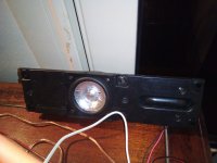
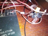
I tried on a fullrange driver which usually is directly connected to the amplifier without crossover that even a small resistance of 0.15 ohms generates an audible difference.
I tried before on the same loudspeaker a 4 ohm fullrange driver, 4 ohms, 2 ohms and one ohm in line.
If the amp has low wattage so even low ohm in series to the driver help the sound playing less distorted.
Some STK chip amps have 0.22 ohms in line at the output. Now I know that this makes a sonic difference.
Attachments
Last edited:

