
Dunno. Different people may have their different reasons they could give.
Some people want to be able to take their dac over to a friend's house without dragging along a computer. Other people just don't like computers.
We like simple DSD converter in some ways, even though we know it could be better. Space is very good. Not quite as smooth sounding as Hqp. (This assumes its reclocked and well isolated; otherwise, not doing those things will reduce SQ.)
OTOH there are lots of different sounds that can be gotten from Hqp, but not sure if any of them are perfectly right. Its a very reasonable choice though.
No dac I have heard so far has ever sounded as good as optical vinyl, but the vinyl rig costs a lot more. Heavier than a computer too.
Last edited:
Hi Joseph 😉
I did try the Amanero but it was some years back and for some reason I couldn't make it work - the playback halted when I used the external clock. However, that is not to say that it doesn't work ... To my memory I (again some years back) read that others have made it work. As it is, however, I also need my DAC to work with my digital piano and the Amanero was not compatible with the software I use ... so, at least for now I use the JLSounds board which, as I mentioned, appears to work flawlessly (haven't tested it with the piano yet, though).
If 2x multiplication is sufficient Marcel has also suggested the XOR 2x multiplier used in the RTZ FIRDAC. Likely a lower phase noise solution ... ?
Cheers, Jesper
So one question emerges in me: did You try Amanero, which by default can work with the 22/24MHz clocks.. Only DSD256, yes.
I did try the Amanero but it was some years back and for some reason I couldn't make it work - the playback halted when I used the external clock. However, that is not to say that it doesn't work ... To my memory I (again some years back) read that others have made it work. As it is, however, I also need my DAC to work with my digital piano and the Amanero was not compatible with the software I use ... so, at least for now I use the JLSounds board which, as I mentioned, appears to work flawlessly (haven't tested it with the piano yet, though).
Multiplier was ICS601-01
If 2x multiplication is sufficient Marcel has also suggested the XOR 2x multiplier used in the RTZ FIRDAC. Likely a lower phase noise solution ... ?
Cheers, Jesper
For Amanero, the right combination of config, firmware is needed but then it's rock solid (I am still using an old model)
Ciao, George
Ciao, George
HP, Ooops You could be right. I did not notice that, but I use Linux (Gentooplayer!) in my systems. For audio. For measurements I use Windows, so I can try there..
I finally completed the 1st RTZ DAC to the updated spec of separate supplies to the filter.

This one has the built-in Squeezebox Receiver innards - which can be seen as the lowest PCB in the stack, underneath the PCM2DSD board. Both this and the Transporter driven one sound virtually identical to my ears. I am now able to make incremental changes to one and compare. It may take me a long time to get around to doing that however! For now I'm just enjoying the music!
This one has the built-in Squeezebox Receiver innards - which can be seen as the lowest PCB in the stack, underneath the PCM2DSD board. Both this and the Transporter driven one sound virtually identical to my ears. I am now able to make incremental changes to one and compare. It may take me a long time to get around to doing that however! For now I'm just enjoying the music!
Hi all,
Well, I am not quite sure what to write ... but I have been working on a layout for Marcel's fine DSD DAC for the last days and I am a bit unsure as how to interpret/understand the clocking layout. And given that bohrok2610 achieved quite remarkable results using a lower phase noise/jitter clock for his DAC I am thinking that optimizing the clock for the LV574s would be feasible, if possible.
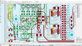
For convenience I have attached a screendump of a part of Marcel's layout for the DAC itself.
What "puzzles" me is the layout for the clock signal going from the LVC2G86 to the LV574s. I will try to outline below "why" (there are many - hopefully relevant, though - thoughts in this so please bear with me if it is not entirely structured). Please also note that I do in no way intend to be "critical" of the layout - but I have given this a lot of thought and I would genuinely appreciate your thoughts/feedback about this ... hope it's not too basic for you ...
...
Anyway, these are the thoughts:
1. The clock traces are running close to the LV574s.
As can be seen on the attached screendump the clock trace e.g. for the lowermost LV574 (U16) goes down perpendicularly along the input side of the LV574. The distance from the clock trace to the LV574's input pins is approx. 3mm. The length of the active input pins on the U16 is approx 5mm (though each of them are horizontal to the clock trace I guess that altogether they constitute a vertical "emitter".)
In Saturn PCB toolkit (called SPT henceforth) the crosstalk coefficient for such a distance and coupled length is -47 dBs. Thus, if all the input pins of the U16 are HIGH at the same time (I know this is not possible but just as an illustration) -47 dB of this ~5 volt level would radiate into the clock trace.
2. No clock trace "guards" ...
Although it seems among various PCB layout sources that guard traces or "GND fence vias" are not unanimously considered feasible (the guard trace appears to be less positively considered at least in a microstrip context) there nevertheless appears to be some consensus that GND fence vias may have some effect (attenuating some 15-25 dBs between the traces that are placed on both sides of the GND fence vias). I reckon such GND fence vias may/might have provided some shielding to the clock traces but they are not there (also, as far as I can see neither in @bohrok2610's layout) ...
Might I ask why?
3. Clock trace/pin is immediately adjacent to one of the FF outputs.
And then ... the clock input pin is immediately adjacent to one of the output pins of the FF. Again, using SPT, a coupled length of 1.75mm (LV574 pin length) spaced 0.18mm apart (spacing between LV574 pins) gives a crosstalk coefficient of -12 dBs ... Thus, whenever the pin12 output of the LV574 is HIGH the level input to the adjacent clock trace is - 12 dB, i.e. approx. 1.25 volts radiated into the clock trace. Although at a lower level(s), something similar should be the case for the other FF output/input pin pairs.
I realize this is not unique for the LV574. As far as I can see almost all logic ICs have their "clock/timing" pins placed immediately adjacent to some other data pin. However, I suppose a key observation here, at least relative to the clock signal, is that this noise only appears after the clock signal has triggered the FF - thus not affecting the clock timing itself if the clock "trace" is well damped between clock pulses, right ... ?
4. Clock trace reflections.
(to Marcel: I realize I have somewhat addressed this in an earlier post which you replied to - yet it is a bit elaborated here).
The LVC2G86s clock doubler (U28) feeds into two resistors of 33 ohms. From there each of the 33 ohm resistors look into a 0.375mm wide trace that is approx. 30mms long. In SPT (trace height above GND layer of 0.2mm & an Er of 4.5) this gives a trace impedance of ~ 47.5 ohms and a trace propagation delay of approx. 180 ps.
Following this 30 mm 47.5 ohm impedance trace, the signal now splits into two trace branches each of which connects directly to the clock pins of the LV574s. These traces have a width of 0.15mm and a length of approx. 23mms. This gives a trace impedance of ~71.6 ohms and a propagation delay of 131 ps.
Assuming that the LVC2G86 has a 17 ohm output impedance this gives three clock trace "sections": A.: the LVC2G86 +33 ohms= ~50ohms, B.: the 47.5 ohm 0.375mm trace, and then C: two branches of 71.6 ohms, i.e. when paralleled 35.8 ohms altogether as seen from the 0.375mm trace.
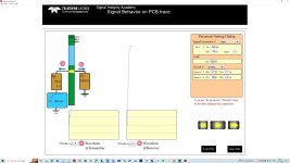
I have tried to enter the values into a signal reflection simulator with a 300 ps rise time (quite basic & easy to work with - https://www.bethesignal.com/bogatin/vrpw3016-yoshi-animations-reflections-p-1072.html)
and as can be seen from the attached screendump the signal trace "breaks up" at approx. 4 volts, i.e. somewhat above the clock trigger point of the LV574s ...
I assume this is the reason why this arrangement works? I.e. that the rising edge of the clock signal reaches the LV574 clock inputs before reflections from the 47.5/35.8 ohms impedance discontinuity can disturb the signal?
And also, since the reflection coefficient between the trace sections B & C is approx. 0.15 (47.5 ohms & 35.8 ohms) ... this means that the reflections caused by the falling edge coming from the LVC2G86 will attenuate sufficiently before the next LVC2G86 rising edge comes. Would this be correct?
5. Crossing traces - crosstalk? - or what happens?
Slightly off-topic as it does not relate to the clock signal layout as such ... actually more in general: When two traces cross perpendicularly on adjacent PCB layers - what is the crosstalk between these traces?
I realize that the currents move perpendicularly relative to each other so from that perspective the crosstalk should be zero ... On the other hand the width of either of the traces relative to each other is a place where induction might happen, thus a "punctual" impedance change, or ... ?? Any of you know about this "in detail"? I haven't really found information about it on the internet ...
6. DSD timing: Daisy chaining & Andrea Mori's DSD DAC.
Well, I cannot say that I know the theory about this but looking at Andrea Mori's DSD DAC (https://www.thewellaudio.com/twsdac-dsd/) I notice there's a bit of way from the clock signal reaches the first "gate/flip flop" until it reaches the FF at the output end of the DAC (going from left to right).
A quick assessment of the time delay (1.5mm thick board, 4 equally spaced layers, 0.7mm trace width, 14 cm trace length from left to right) is that it takes appr. 0.8 ns for the clock signal to travel from the left to the right of the board.
This appears to be somewhat "opposing" to the focus on femto-second and pico-second oscillators although I realize that such precise oscillators may still ensure period-to-period precision. And @bohrok2610's results also showed the importance of a good oscillator ...
Anyway, in relation to Marcel's DSD DAC: Wouldn't it make life "easier" on the clock doubling LVC2G86 if e.g. each of the output LV574 pairs were daisy chained, i.e. first going to the first LV574 and then to the second in a pair? This would give a delay between the two clocks of appr. 120 ps ... yet cause "no or less" reflections in the clock traces ...
7. Why this layout works - multipla of the signal?
Marcel has previously hinted at that when interfering signals are a multipla of the clock signal they may not disturb the conversion process (I hope I have understood this correctly). Considering that there are so many high & low level clock noise sources in this DAC (and in other DACs, I assume) ... is one possible reason that it doesn't really affect the output distortion or noise levels (it still might, I guess, but bohrok2610's results IMHO were outstanding) that they are all related to the clock frequency and thus at least to some extent "cyclical"?
Or, that the clock signal reaches its "destination(s)" before the noise sources may influence the clock signal (and these noises are then attenuated before the next clock signal comes)?
Phew, I think this is the longest post I have ever made here on diyaudio (if you made it to here, thanks for reading 😉) ... but my feel/intuition is that ensuring low jitter in digital converters may be key to their sound quality - and thus, as well as I may, I have given this topic some thought over time.
And in the context of the fine performance of Marcel's DAC - and here returning to the top sentences of this post - I think it could be interesting to optimize, if possible, its clock performance.
Any thoughts, comments, ideas ... ?
Cheers,
Jesper
Well, I am not quite sure what to write ... but I have been working on a layout for Marcel's fine DSD DAC for the last days and I am a bit unsure as how to interpret/understand the clocking layout. And given that bohrok2610 achieved quite remarkable results using a lower phase noise/jitter clock for his DAC I am thinking that optimizing the clock for the LV574s would be feasible, if possible.
For convenience I have attached a screendump of a part of Marcel's layout for the DAC itself.
What "puzzles" me is the layout for the clock signal going from the LVC2G86 to the LV574s. I will try to outline below "why" (there are many - hopefully relevant, though - thoughts in this so please bear with me if it is not entirely structured). Please also note that I do in no way intend to be "critical" of the layout - but I have given this a lot of thought and I would genuinely appreciate your thoughts/feedback about this ... hope it's not too basic for you
...Anyway, these are the thoughts:
1. The clock traces are running close to the LV574s.
As can be seen on the attached screendump the clock trace e.g. for the lowermost LV574 (U16) goes down perpendicularly along the input side of the LV574. The distance from the clock trace to the LV574's input pins is approx. 3mm. The length of the active input pins on the U16 is approx 5mm (though each of them are horizontal to the clock trace I guess that altogether they constitute a vertical "emitter".)
In Saturn PCB toolkit (called SPT henceforth) the crosstalk coefficient for such a distance and coupled length is -47 dBs. Thus, if all the input pins of the U16 are HIGH at the same time (I know this is not possible but just as an illustration) -47 dB of this ~5 volt level would radiate into the clock trace.
2. No clock trace "guards" ...
Although it seems among various PCB layout sources that guard traces or "GND fence vias" are not unanimously considered feasible (the guard trace appears to be less positively considered at least in a microstrip context) there nevertheless appears to be some consensus that GND fence vias may have some effect (attenuating some 15-25 dBs between the traces that are placed on both sides of the GND fence vias). I reckon such GND fence vias may/might have provided some shielding to the clock traces but they are not there (also, as far as I can see neither in @bohrok2610's layout) ...
Might I ask why?
3. Clock trace/pin is immediately adjacent to one of the FF outputs.
And then ... the clock input pin is immediately adjacent to one of the output pins of the FF. Again, using SPT, a coupled length of 1.75mm (LV574 pin length) spaced 0.18mm apart (spacing between LV574 pins) gives a crosstalk coefficient of -12 dBs ... Thus, whenever the pin12 output of the LV574 is HIGH the level input to the adjacent clock trace is - 12 dB, i.e. approx. 1.25 volts radiated into the clock trace. Although at a lower level(s), something similar should be the case for the other FF output/input pin pairs.
I realize this is not unique for the LV574. As far as I can see almost all logic ICs have their "clock/timing" pins placed immediately adjacent to some other data pin. However, I suppose a key observation here, at least relative to the clock signal, is that this noise only appears after the clock signal has triggered the FF - thus not affecting the clock timing itself if the clock "trace" is well damped between clock pulses, right ... ?
4. Clock trace reflections.
(to Marcel: I realize I have somewhat addressed this in an earlier post which you replied to - yet it is a bit elaborated here).
The LVC2G86s clock doubler (U28) feeds into two resistors of 33 ohms. From there each of the 33 ohm resistors look into a 0.375mm wide trace that is approx. 30mms long. In SPT (trace height above GND layer of 0.2mm & an Er of 4.5) this gives a trace impedance of ~ 47.5 ohms and a trace propagation delay of approx. 180 ps.
Following this 30 mm 47.5 ohm impedance trace, the signal now splits into two trace branches each of which connects directly to the clock pins of the LV574s. These traces have a width of 0.15mm and a length of approx. 23mms. This gives a trace impedance of ~71.6 ohms and a propagation delay of 131 ps.
Assuming that the LVC2G86 has a 17 ohm output impedance this gives three clock trace "sections": A.: the LVC2G86 +33 ohms= ~50ohms, B.: the 47.5 ohm 0.375mm trace, and then C: two branches of 71.6 ohms, i.e. when paralleled 35.8 ohms altogether as seen from the 0.375mm trace.
I have tried to enter the values into a signal reflection simulator with a 300 ps rise time (quite basic & easy to work with - https://www.bethesignal.com/bogatin/vrpw3016-yoshi-animations-reflections-p-1072.html)
and as can be seen from the attached screendump the signal trace "breaks up" at approx. 4 volts, i.e. somewhat above the clock trigger point of the LV574s ...
I assume this is the reason why this arrangement works? I.e. that the rising edge of the clock signal reaches the LV574 clock inputs before reflections from the 47.5/35.8 ohms impedance discontinuity can disturb the signal?
And also, since the reflection coefficient between the trace sections B & C is approx. 0.15 (47.5 ohms & 35.8 ohms) ... this means that the reflections caused by the falling edge coming from the LVC2G86 will attenuate sufficiently before the next LVC2G86 rising edge comes. Would this be correct?
5. Crossing traces - crosstalk? - or what happens?
Slightly off-topic as it does not relate to the clock signal layout as such ... actually more in general: When two traces cross perpendicularly on adjacent PCB layers - what is the crosstalk between these traces?
I realize that the currents move perpendicularly relative to each other so from that perspective the crosstalk should be zero ... On the other hand the width of either of the traces relative to each other is a place where induction might happen, thus a "punctual" impedance change, or ... ?? Any of you know about this "in detail"? I haven't really found information about it on the internet ...
6. DSD timing: Daisy chaining & Andrea Mori's DSD DAC.
Well, I cannot say that I know the theory about this but looking at Andrea Mori's DSD DAC (https://www.thewellaudio.com/twsdac-dsd/) I notice there's a bit of way from the clock signal reaches the first "gate/flip flop" until it reaches the FF at the output end of the DAC (going from left to right).
A quick assessment of the time delay (1.5mm thick board, 4 equally spaced layers, 0.7mm trace width, 14 cm trace length from left to right) is that it takes appr. 0.8 ns for the clock signal to travel from the left to the right of the board.
This appears to be somewhat "opposing" to the focus on femto-second and pico-second oscillators although I realize that such precise oscillators may still ensure period-to-period precision. And @bohrok2610's results also showed the importance of a good oscillator ...
Anyway, in relation to Marcel's DSD DAC: Wouldn't it make life "easier" on the clock doubling LVC2G86 if e.g. each of the output LV574 pairs were daisy chained, i.e. first going to the first LV574 and then to the second in a pair? This would give a delay between the two clocks of appr. 120 ps ... yet cause "no or less" reflections in the clock traces ...
7. Why this layout works - multipla of the signal?
Marcel has previously hinted at that when interfering signals are a multipla of the clock signal they may not disturb the conversion process (I hope I have understood this correctly). Considering that there are so many high & low level clock noise sources in this DAC (and in other DACs, I assume) ... is one possible reason that it doesn't really affect the output distortion or noise levels (it still might, I guess, but bohrok2610's results IMHO were outstanding) that they are all related to the clock frequency and thus at least to some extent "cyclical"?
Or, that the clock signal reaches its "destination(s)" before the noise sources may influence the clock signal (and these noises are then attenuated before the next clock signal comes)?
Phew, I think this is the longest post I have ever made here on diyaudio (if you made it to here, thanks for reading 😉) ... but my feel/intuition is that ensuring low jitter in digital converters may be key to their sound quality - and thus, as well as I may, I have given this topic some thought over time.
And in the context of the fine performance of Marcel's DAC - and here returning to the top sentences of this post - I think it could be interesting to optimize, if possible, its clock performance.
Any thoughts, comments, ideas ... ?
Cheers,
Jesper
Attachments
Thanks for you very elaborate study. I have never gone into such depths in analyzing layouts. I usually follow just few guidelines.
Hopefully Marcel can answer your other questions.
/Martti
I do not normally use guard traces or via fences. Guard traces are not considered very effective (see e.g. https://resources.altium.com/p/guard-traces-hit-or-myth). Via fences probably work better but they take up lots of PCB real estate. I usually try to make compact boards as this helps in keeping traces short. Crosstalk can be mitigated by keeping traces well separated (i.e. more than minimum spacing). I also try to route clock (or other sensitive) signals so that they are over a continuous plane (GND or VDD) without any other traces crossing the path.2. No clock trace "guards"
Hopefully Marcel can answer your other questions.
/Martti
Hi Martti,
Thanks for your feedback. And, yes, it has been an elaborate process of going through these considerations. Something which in the context of Marcel's DAC (and your layout), has been quite interesting because the theory (I know of) and practice appear to somewhat "challenge" each other.
That is also my impression particularly in a microstrip trace. Thanks otherwise for your layout feedback ;-)
Cheers, Jesper
Thanks for your feedback. And, yes, it has been an elaborate process of going through these considerations. Something which in the context of Marcel's DAC (and your layout), has been quite interesting because the theory (I know of) and practice appear to somewhat "challenge" each other.
Guard traces are not considered very effective
That is also my impression particularly in a microstrip trace. Thanks otherwise for your layout feedback ;-)
Cheers, Jesper
Jesper,
Regarding your item 6, the FF outputs are combined along that wide bus to form the analog audio output. It would seem that what matters at that point is that for each FF, the output pulse width and amplitude are accurate (pulse area under the curve is correct). Any small-ish (~.8ns), consistent time offsets (skew) in absolute pulse edge start time at that point are going to be averaged out as the audio is LP filtered.
Cheers,
Mark
Last edited:
Considering the optocouplers on that board used for datalines have part-to-part skew of 20ns (+-10ns) I would not be too worried about the 0.8ns offset in DCLK.
Reclocking occurs after the optocouplers. The optocouplers are to prevent ground loops and other CM noise from getting into the dac. There is only one ground from the FIFO board to the dac. It is the MCLK coax ground (MCLK is not optocoupled).
I'm sure they were measured in the actual circuit and found to have a reliable timing margin.
Marcel may have cut the timing margin closer in his RTZ dac.
Marcel may have cut the timing margin closer in his RTZ dac.
Sorry, but as these signals come from external sources the timing margin cannot be predetermined.
Hi Mark,
I have also considered this, and additionally, that since there are so many taps on Andrea's DSD DAC that there are likely also many notches in the HF response (giving HF attenuation) that may further alleviate the need for individual tap clock precision. Anyway, it is beyond me to calculate if this may actually be the case. However, I do remember from reading parts of Schreier's book on delta sigma conversion years ago that particularly one of the Delta-Sigma types (continuous time converter?) was very sensitive to clock jitter.
In any case I am just trying to find out how/what causes Martti's converter - with a better clock - to perform as good as it does.
Have a fine day ...
Jesper
Regarding your item 6, the FF outputs are combined along that wide bus to form the analog audio output. It would seem that what matters at that point is that for each FF, the output pulse width and amplitude are accurate (pulse area under the curve is correct). Any small-ish (~.8ns), consistent time offsets (skew) in absolute pulse edge start time at that point are going to be averaged out as the audio is LP filtered.
I have also considered this, and additionally, that since there are so many taps on Andrea's DSD DAC that there are likely also many notches in the HF response (giving HF attenuation) that may further alleviate the need for individual tap clock precision. Anyway, it is beyond me to calculate if this may actually be the case. However, I do remember from reading parts of Schreier's book on delta sigma conversion years ago that particularly one of the Delta-Sigma types (continuous time converter?) was very sensitive to clock jitter.
In any case I am just trying to find out how/what causes Martti's converter - with a better clock - to perform as good as it does.
Have a fine day ...
Jesper
... And then a comment for Marcel: Although I am aware that parts of my long post above likely is best answered by you I would like to say that I do not expect you to reply. Please feel welcome to just let me know if for whatever reason it is more feasible for you to not reply.
Cheers, Jesper
Cheers, Jesper
Hi Jesper,
Thanks for your detailed analysis. It is very well possible that the layout leaves room for improvement. I never looked into it quite as detailed as you.
There is in fact something in the design that should also be improved, namely the hold time of the D0 and D1 inputs of the SN74LV574As. Measurements from Markw4 show that the delay of U22, U24, U26 and U27 is less than what I counted on; their datasheet specification is for a capacitive load of 50 pF, but there is no such load. I think it will suffice to replace R124, R127, R129 and R131 with higher values and use the trace and input capacitance to get a nanosecond or two of extra delay, but I still have to look into it.
Does that take into account the ground fill on the top copper layer and the ground plane on the second layer? I was under the impression I had taken a comfortable distance between the clock trace and the 74LV574As, but I may be wrong, as I never tried to estimate the crosstalk.

There is ground fill in the upper layer with vias to the ground plane in layer 2. The vias could be placed more regularly and closer to the clock trace. Via stitching is a bit of a pain with the antique KiCad version I use.
Under what conditions does that -12 dB apply? What are the assumptions about transition times and driving impedances?
It will indeed be a short peak after the clock edge. Any remaining effect will also balance out to some extent; U14 and U16 process the same data, and in each bit clock cycle, there is always one of them that gets a 1 on Q0 and one that doesn't.
I think so. By the way, you always have a discontinuity where the trace reaches the packages of the logic ICs.
I think it will depend on where the return currents of the signals have to flow. Are there ground planes on either side of the crossing signals?
I never tried, but maybe you can calculate the inductive coupling with the Greenhouse method, see Harold Greenhouse, "Design of planar rectangular microelectronic inductors", IEEE Transactions on Parts, Hybrids and Packaging, July 1974, pages 101...109, https://www.researchgate.net/public...nic_inductors_IEEE_Trans_Parts_Hybrids_Packag
If the distance is small compared to the width of the traces, you could estimate the capacitive coupling by assuming that the part where the traces are on top of each other is a large plate capacitor.
More accurate would be using an EM simulator of some sort.
The waveform of the current drawn from the reference then becomes data-dependent; the peaks occur 120 ps sooner or later depending on the data. I would expect that to cause extra mixing of out-of-band quantization noise into the audio band, but don't ask me how much.
Yes, you have.
The data signals have other frequency components than just multiples of the clock frequency, so they can disturb the clock in ways that affect the conversion. Like I wrote, I think those effects are cancelled to some extent due to the balanced nature of the DAC.
Yes, that sounds like a good hypothesis.
Regards,
Marcel
Thanks for your detailed analysis. It is very well possible that the layout leaves room for improvement. I never looked into it quite as detailed as you.
There is in fact something in the design that should also be improved, namely the hold time of the D0 and D1 inputs of the SN74LV574As. Measurements from Markw4 show that the delay of U22, U24, U26 and U27 is less than what I counted on; their datasheet specification is for a capacitive load of 50 pF, but there is no such load. I think it will suffice to replace R124, R127, R129 and R131 with higher values and use the trace and input capacitance to get a nanosecond or two of extra delay, but I still have to look into it.
What "puzzles" me is the layout for the clock signal going from the LVC2G86 to the LV574s. I will try to outline below "why" (there are many - hopefully relevant, though - thoughts in this so please bear with me if it is not entirely structured). Please also note that I do in no way intend to be "critical" of the layout - but I have given this a lot of thought and I would genuinely appreciate your thoughts/feedback about this ... hope it's not too basic for you
Anyway, these are the thoughts:
1. The clock traces are running close to the LV574s.
As can be seen on the attached screendump the clock trace e.g. for the lowermost LV574 (U16) goes down perpendicularly along the input side of the LV574. The distance from the clock trace to the LV574's input pins is approx. 3mm. The length of the active input pins on the U16 is approx 5mm (though each of them are horizontal to the clock trace I guess that altogether they constitute a vertical "emitter".)
In Saturn PCB toolkit (called SPT henceforth) the crosstalk coefficient for such a distance and coupled length is -47 dBs. Thus, if all the input pins of the U16 are HIGH at the same time (I know this is not possible but just as an illustration) -47 dB of this ~5 volt level would radiate into the clock trace.
Does that take into account the ground fill on the top copper layer and the ground plane on the second layer? I was under the impression I had taken a comfortable distance between the clock trace and the 74LV574As, but I may be wrong, as I never tried to estimate the crosstalk.
2. No clock trace "guards" ...
Although it seems among various PCB layout sources that guard traces or "GND fence vias" are not unanimously considered feasible (the guard trace appears to be less positively considered at least in a microstrip context) there nevertheless appears to be some consensus that GND fence vias may have some effect (attenuating some 15-25 dBs between the traces that are placed on both sides of the GND fence vias). I reckon such GND fence vias may/might have provided some shielding to the clock traces but they are not there (also, as far as I can see neither in @bohrok2610's layout) ...
Might I ask why?
There is ground fill in the upper layer with vias to the ground plane in layer 2. The vias could be placed more regularly and closer to the clock trace. Via stitching is a bit of a pain with the antique KiCad version I use.
3. Clock trace/pin is immediately adjacent to one of the FF outputs.
And then ... the clock input pin is immediately adjacent to one of the output pins of the FF. Again, using SPT, a coupled length of 1.75mm (LV574 pin length) spaced 0.18mm apart (spacing between LV574 pins) gives a crosstalk coefficient of -12 dBs ... Thus, whenever the pin12 output of the LV574 is HIGH the level input to the adjacent clock trace is - 12 dB, i.e. approx. 1.25 volts radiated into the clock trace. Although at a lower level(s), something similar should be the case for the other FF output/input pin pairs.
I realize this is not unique for the LV574. As far as I can see almost all logic ICs have their "clock/timing" pins placed immediately adjacent to some other data pin. However, I suppose a key observation here, at least relative to the clock signal, is that this noise only appears after the clock signal has triggered the FF - thus not affecting the clock timing itself if the clock "trace" is well damped between clock pulses, right ... ?
Under what conditions does that -12 dB apply? What are the assumptions about transition times and driving impedances?
It will indeed be a short peak after the clock edge. Any remaining effect will also balance out to some extent; U14 and U16 process the same data, and in each bit clock cycle, there is always one of them that gets a 1 on Q0 and one that doesn't.
4. Clock trace reflections.
(to Marcel: I realize I have somewhat addressed this in an earlier post which you replied to - yet it is a bit elaborated here).
The LVC2G86s clock doubler (U28) feeds into two resistors of 33 ohms. From there each of the 33 ohm resistors look into a 0.375mm wide trace that is approx. 30mms long. In SPT (trace height above GND layer of 0.2mm & an Er of 4.5) this gives a trace impedance of ~ 47.5 ohms and a trace propagation delay of approx. 180 ps.
Following this 30 mm 47.5 ohm impedance trace, the signal now splits into two trace branches each of which connects directly to the clock pins of the LV574s. These traces have a width of 0.15mm and a length of approx. 23mms. This gives a trace impedance of ~71.6 ohms and a propagation delay of 131 ps.
Assuming that the LVC2G86 has a 17 ohm output impedance this gives three clock trace "sections": A.: the LVC2G86 +33 ohms= ~50ohms, B.: the 47.5 ohm 0.375mm trace, and then C: two branches of 71.6 ohms, i.e. when paralleled 35.8 ohms altogether as seen from the 0.375mm trace.
I have tried to enter the values into a signal reflection simulator with a 300 ps rise time (quite basic & easy to work with - https://www.bethesignal.com/bogatin/vrpw3016-yoshi-animations-reflections-p-1072.html)
and as can be seen from the attached screendump the signal trace "breaks up" at approx. 4 volts, i.e. somewhat above the clock trigger point of the LV574s ...
I assume this is the reason why this arrangement works? I.e. that the rising edge of the clock signal reaches the LV574 clock inputs before reflections from the 47.5/35.8 ohms impedance discontinuity can disturb the signal?
And also, since the reflection coefficient between the trace sections B & C is approx. 0.15 (47.5 ohms & 35.8 ohms) ... this means that the reflections caused by the falling edge coming from the LVC2G86 will attenuate sufficiently before the next LVC2G86 rising edge comes. Would this be correct?
I think so. By the way, you always have a discontinuity where the trace reaches the packages of the logic ICs.
5. Crossing traces - crosstalk? - or what happens?
Slightly off-topic as it does not relate to the clock signal layout as such ... actually more in general: When two traces cross perpendicularly on adjacent PCB layers - what is the crosstalk between these traces?
I realize that the currents move perpendicularly relative to each other so from that perspective the crosstalk should be zero ... On the other hand the width of either of the traces relative to each other is a place where induction might happen, thus a "punctual" impedance change, or ... ?? Any of you know about this "in detail"? I haven't really found information about it on the internet ...
I think it will depend on where the return currents of the signals have to flow. Are there ground planes on either side of the crossing signals?
I never tried, but maybe you can calculate the inductive coupling with the Greenhouse method, see Harold Greenhouse, "Design of planar rectangular microelectronic inductors", IEEE Transactions on Parts, Hybrids and Packaging, July 1974, pages 101...109, https://www.researchgate.net/public...nic_inductors_IEEE_Trans_Parts_Hybrids_Packag
If the distance is small compared to the width of the traces, you could estimate the capacitive coupling by assuming that the part where the traces are on top of each other is a large plate capacitor.
More accurate would be using an EM simulator of some sort.
6. DSD timing: Daisy chaining & Andrea Mori's DSD DAC.
Well, I cannot say that I know the theory about this but looking at Andrea Mori's DSD DAC (https://www.thewellaudio.com/twsdac-dsd/) I notice there's a bit of way from the clock signal reaches the first "gate/flip flop" until it reaches the FF at the output end of the DAC (going from left to right).
A quick assessment of the time delay (1.5mm thick board, 4 equally spaced layers, 0.7mm trace width, 14 cm trace length from left to right) is that it takes appr. 0.8 ns for the clock signal to travel from the left to the right of the board.
This appears to be somewhat "opposing" to the focus on femto-second and pico-second oscillators although I realize that such precise oscillators may still ensure period-to-period precision. And @bohrok2610's results also showed the importance of a good oscillator ...
Anyway, in relation to Marcel's DSD DAC: Wouldn't it make life "easier" on the clock doubling LVC2G86 if e.g. each of the output LV574 pairs were daisy chained, i.e. first going to the first LV574 and then to the second in a pair? This would give a delay between the two clocks of appr. 120 ps ... yet cause "no or less" reflections in the clock traces ...
The waveform of the current drawn from the reference then becomes data-dependent; the peaks occur 120 ps sooner or later depending on the data. I would expect that to cause extra mixing of out-of-band quantization noise into the audio band, but don't ask me how much.
7. Why this layout works - multipla of the signal?
Marcel has previously hinted at that when interfering signals are a multipla of the clock signal they may not disturb the conversion process (I hope I have understood this correctly).
Yes, you have.
Considering that there are so many high & low level clock noise sources in this DAC (and in other DACs, I assume) ... is one possible reason that it doesn't really affect the output distortion or noise levels (it still might, I guess, but bohrok2610's results IMHO were outstanding) that they are all related to the clock frequency and thus at least to some extent "cyclical"?
The data signals have other frequency components than just multiples of the clock frequency, so they can disturb the clock in ways that affect the conversion. Like I wrote, I think those effects are cancelled to some extent due to the balanced nature of the DAC.
Or, that the clock signal reaches its "destination(s)" before the noise sources may influence the clock signal (and these noises are then attenuated before the next clock signal comes)?
Yes, that sounds like a good hypothesis.
Phew, I think this is the longest post I have ever made here on diyaudio (if you made it to here, thanks for reading 😉) ... but my feel/intuition is that ensuring low jitter in digital converters may be key to their sound quality - and thus, as well as I may, I have given this topic some thought over time.
And in the context of the fine performance of Marcel's DAC - and here returning to the top sentences of this post - I think it could be interesting to optimize, if possible, its clock performance.
Any thoughts, comments, ideas ... ?
Cheers,
Jesper
Regards,
Marcel
- Home
- Source & Line
- Digital Line Level
- Return-to-zero shift register FIRDAC