Old thread but finally getting around to it... Have a question that maybe be obvious but as I'm new to reading schematics, I wanted to double check with the community. Looking at the power supply, does the section outlined in red (the 7.5K resistor and 10uF cap) need to be repeated on each channel in a stereo build? Or just once in the power supply? I read it as an additional filter for the input driver tubes and have imagined it implemented once in the PS and the B+ would go from the juncion of the 7.5K resistor and 10uF cap to the plate of each 12AT7. Does that seem right? Thanks in advance.

Just out of curiosity... how does that effect the circuit vs. having the 7.5k resistor and 10uF cap feed both 12AT7s?
I Should preface this with the fact that I'm new to building with only a schematic in front of me.
In my mind - in a stereo configuration - the 350V B+ would be pulled from the 390k resistor in the power supply and run to the output transformers and then the 2A3s. The B+ for the 12AT7s would come from the junction of the .5k resistor and 10uF cap and continue to both driver tubes.
Here to learn!
Caution:
1. If one 12AT7 triode is not well matched to the other 12AT7 triode, then . . .
The Stronger triode will hog current, and the weaker triode will be starving for current.
I hope that explains the need for:
Either very well matched 12AT7 triodes
Or for Two separate 7.5k and 10uF caps
If you Do decide to use a single resistor from the B+, it needs to be 7.5k / 2 = 3.75k Ohms (and use a 20uF bypass cap instead of a 10uF cap).
2. The 390k and 100k resistor is for elevating the 12AT7 filaments (to preserve the top triode's filament to cathode insulation properties).
It will work fine for a stereo version, unless you have a bad 12AT7 (filament to cathode leakage). If there is filament to cathode leakage, then replace that tube.
"You should make things as simple as possible, but no simpler" - Albert Einstein
Happy Building and Happy Listening!
Last edited:
This makes sense. My 12AT7s are matched… regardless as long as there is space, two 7.5k and 10uF parts is the way to go. That said, my power tubes are matched… broadly speaking, would this same consideration be paid to them as well?1. If one 12AT7 triode is not well matched to the other 12AT7 triode, then . . .
The Stronger triode will hog current, and the weaker triode will be starving for current.
This I understand and will do a virtual center tap on the 6.3V secondary with two 100 Ohm resistors and eventually continue on to the 12AT7s.2. The 390k and 100k resistor is for elevating the 12AT7 filaments (to preserve the top triode's filament to cathode insulation properties).
It will work fine for a stereo version, unless you have a bad 12AT7 (filament to cathode leakage). If there is filament to cathode leakage, then replace that tube.
joneci,
Your 2A3 tubes are individually self biased.
Each 2A3 has 1k and 30uF.
The self bias is 50V across 1k, and that is 50mA
That is OK.
But the Baby Ongaku are Mono-Blocks.
That means the B+ is made for the current draw of One 2A3 (50mA), and the 12AT7 (4.5mA for the SRPP), and the small current for the 330k/100k series string (about 1mA). The total is about 56mA.
The monoblock 14H choke is rated for 75mA.
A stereo amp will draw about 112mA; much more than the choke is rated for.
And for the same ripple voltage, you will need 2 x 0.68uF, and 2 x 100uF, and a 150mA or 200mA 14H choke.
The 5V4 can easily provide 112mA.
Be sure your health insurance includes free Hernia Operations, or build mono-blocks.
The choke I have on hand is 15H and rated at 200mA (240mA max) so it should be fine for the stereo version. Yes it will be heavy but I'll lift with the legs!But the Baby Ongaku are Mono-Blocks.
That means the B+ is made for the current draw of One 2A3 (50mA), and the 12AT7 (4.5mA for the SRPP), and the small current for the 330k/100k series string (about 1mA). The total is about 56mA.
The monoblock 14H choke is rated for 75mA.
To be clear, for the 12AT7, as long as I have 350V on the B+ at the OPT, I should be able to keep the schematic as is with a 7.5k resistor and 10uF cap on each tube and call it a day. Right?
Isn't the .68uF just there to "tune" the B+? From what I understand, doubling the first capacitor will raise the B+ and as far as I can tell the voltage would be much higher than the 350V required.A stereo amp will draw about 112mA; much more than the choke is rated for.
And for the same ripple voltage, you will need 2 x 0.68uF, and 2 x 100uF, and a 150mA or 200mA 14H choke.
Also, I guess this is where PS design is a bit confusing for a noob. For a stereo PS I'm not quite clear on why you would have to double the 100uF... I understand that there is double the current...
Yes, a separate 7.5k resistor and 10uF cap for each channel's 12AT7.
Yes, the B+ is a modified choke input power supply (the modification is the addition of the 0.68uF cap to adjust for 350V).
A 0.68 uF capacitor has ripple voltage according to the voltage from the rectifier tube, and the current draw of the amplifier.
The average voltage of that ripple voltage determines the voltage from the choke.
Mono-Block: One 0.68uF capacitor, according to the 56mA current draw, gives about 350V.
Stereo: Two 0.68uF capacitors in parallel, according to the 112mA current draw gives about 350V. (A 1 uF or 1.5uF cap will probably be needed)
The ripple voltage of the 0.68, 14H or 15H, and 100uF is determined by the 56mA current draw. A 112mA draw will have more ripple voltage.
And, the voltage variation of the B+ with more signal current (stereo 2A3s) will vary more with 100uF than it will with 200uF.
Just trying to make the stereo amp sound like 2 mono-block amps.
Since you are going to need two 7.5k resistors and two 10uf caps, just give each 12AT7 it's own supply, or is that what you meant?This makes sense. My 12AT7s are matched… regardless as long as there is space, two 7.5k and 10uF parts is the way to go. That said, my power tubes are matched… broadly speaking, would this same consideration be paid to them as well?
This I understand and will do a virtual center tap on the 6.3V secondary with two 100 Ohm resistors and eventually continue on to the 12AT7s.
Either a 7.5k and 10uF network for each 12AT7, that is best if the 2 SRPP stages are not well matched,
Or . . .
A single 3.75k and 20uF network to run both 12AT7 tubes.
The +350V connects to the B+ tap of each output transformer power supply.
If you are going to use 2 power transformers, 2 tube rectifiers, and 2 of everything else, you need 2 chassis, and are already on your way to building 2 mono-blocks.
I was not leading to that.
They'll each get their own resistor and cap.Since you are going to need two 7.5k resistors and two 10uf caps, just give each 12AT7 it's own supply, or is that what you meant?
One power transformer, one 5AR4, one choke and two of everything else! Heavy for sure but couldn't afford to double up on the PT and choke. The 350V B+ will continue to the left and right OPT then off to the 7.5k and 10uF for each 12AT7 and through to the plates of the 2A3s. Rough version of the PS below. Will need to tweak the little cap to get the B+ right on.If you are going to use 2 power transformers, 2 tube rectifiers, and 2 of everything else, you need 2 chassis, and are already on your way to building 2 mono-blocks.
I was not leading to that.

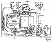
This old thread but a new question as I'm about to dive in and it's specific to the design of the PS in the Baby Ongaku. I've attached the schematic again as a reference.
The PS has a small capacitor before the choke to slightly raise the B+ voltage... this seems to exist firmly between a capacitor input and choke input. So which is it?
I ask because I have a couple of chokes to choose from and wonder if this one would work (see specs below).
Rating 15H 150mA
Max Current 200mA
DC Resistance 165Ω
It's not sold as a choke input specifically, but the specs seem to fit the needs of the Baby Ongaku PS... this gets back to my question... is it a choke input or a capacitor input? And would this choke work?
Thanks in advance!
The Baby Ongaku design operates the 2A3 at 300V plate to filament, and 50mA (15 Watts plate dissipation).
We can expect the max current of the 2A3 to be 50mA quiescent + (1.2 x 50mA) = 110mA peak current when the amplifier is played as loud as you can stand it versus the distortion you get at that power out.
The 100uF cap that is after the choke smooths (averages) all that out for the 2A3 B+. Remember, when you have the volume turned up, you get up to 110mA current in one direction of the signal swing, but on the other direction of the signal swing, you get 5 or 10mA.
For a monoblock, and 110mA, your 15H 150mA choke will be OK.
Not a good idea for a stereo 2A3 amplifier.
I really like choke input B+ filters, but sometimes I use a low capacitance before the choke, 0.5uF to up to 2uF.
I call this a modified choke input filter (others might not).
The result is much closer to a choke input filter, versus a cap input filter (like one that uses 20uF or more).
Hopefully you will get the amplifier built soon; so we can hear from you how pleased you are with the sound.
I like the fact that most of my amplifiers are mono-blocks, I only have to finish one, measure, and listen. The sound motivates me to build the second mono-block.
My voltage might be a touch high coming out of the rectifier, so wonder if the choke will fare well without the .68uF cap. I only ask because there are chokes sold as both cap input and choke input. Again the specs that I have seem to suggest it will be fine, but the choke I’m looking at isn’t specified as a choke input.For a monoblock, and 110mA, your 15H 150mA choke will be OK.
Not a good idea for a stereo 2A3 amplifier.
I really like choke input B+ filters, but sometimes I use a low capacitance before the choke, 0.5uF to up to 2uF.
I call this a modified choke input filter (others might not).
The result is much closer to a choke input filter, versus a cap input filter (like one that uses 20uF or more).
Do you use the small cap before the choke to adjust the B+ or for some other reason?
Thanks and getting there!
Hello,
My phone to small to read the circuit. But a good quality choke should work with choke input too.
Just a small cap will already give a much higher dc. With a true choke input your dc voltage will always be lower than the ac voltage from the transformer. You can get a lower dc voltage by using a smaller cap. People will tell you it has to be a high quality cap and that is true.
They will tell you to minimise cabling to this cap and not create a loop.
Greetings Eduard
What is the loaded Vrms of the B+ secondary, end to center tap?
For a choke input power supply, DC Volts out = 0.9 x Vrms
A loaded 350V-0-350V secondary gives 0.9x 350 = 315V
That does not include the voltage drops of the tube rectifier, the DCR of the choke, and the resistor in a LCRC B+ filter.
So the DC volts will be less than 315V.
I only use the 0.5uF to 2uF before a choke input supply to adjust for the B+ voltage I want.
And yes, technically it is not a choke input supply, but has most of the characteristics of a choke input supply.
The power transformers runs cooler when the cap following the rectifier is a 2uF; instead of the typical cap input of 10, 20, 40, or 60uF.
Hello,
The previous poster will confirm that keeping the first cap small will give the rectifier an easier life.
The power transformer running cooling shows that the big charging current typical for cap input supply are greatly reduced and i have read these currents are way bigger than the current drawn by the circuit.
Still hard to understand why people don't go for choke input more often. Yes you need more ac output from the transformer but the va rating can be similar because the current being drawn is steady.
Greetings Eduard
This old thread but a new relevant question... There is no information regarding the choke except that it is 14H and rated at 75mA. I might end up making these monoblocks (as designed) and have found a reasonably priced 16H capacitor input choke that's rated for 120mA (150mA max) and 500VDC. In this circuit with a small input cap before the choke, do I need a choke that is explicitly designed for a choke input? Or will the one that I found work?
Thanks!

Thanks!
I would be surprised that any decent 16H 120mA rated choke would hum if it was preceded with 0.68uF.
120Hz full wave:
16H = 12k Ohms Xl
0.68uF = 1950 Ohms Xc
For a 60mA load, the ripple across the 0.68uF cap will be about 117V peak to peak. A quality choke should be able to handle 117VAC across it.
Wow!
A good idea . . . connect your 16H choke directly across your 120VAC power mains, and see if it hums.
120VAC = 170V peak
170V / 12k Ohms = 14mA peak through the choke.
Caution: Be sure to connect a 25k 5 Watt resistor across the choke; that way when you disconnect the choke from 120VAC, the magnetic stored energy has a place to go, instead of the un-terminated current causes high voltage, and the resultant Arcing across the choke.
Only actual testing; or building and listening will tell for sure if the choke is silent.
. . . Making Calibrated Measurements since 1959.
Trust but Verify.
Where have I heard that before?
Have Fun!
Last edited:
I just can't let this go... I haven't been able to find a decent-sized or priced choke that is specifically designed for a choke input filter. All of them are either huge or very expensive. Looking at the layout for the Baby Ongaku by Don Garber (see attached), it's hard to imagine the choke pictured is similar to the massive 15H chokes I see that are specified as choke input chokes. Yes, the drawing isn't to scale and this impression is wholly unscientific, but it seems sized for a high-quality traditional choke.
Considering the small tuning cap before the choke... and as a couple of people have mentioned, a high-quality choke should work, no?
I have two Tango 15H 150mA chokes with 155 Ohm DCR that I'd love to use and I plan to give these a shot in the circuit, but want to make sure I won't damage the chokes in the process.
Attachments
- Home
- Amplifiers
- Tubes / Valves
- Help to understand and adapt Baby Ongaku PS to suit my power transformer...