I have zero knowledge of class a/b amps.
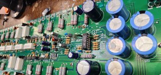
This amp was drawing current.
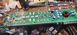
I found 2 dead transistors in the output section. After removing them the amp will no longer power up at all.
I put replacements in and still nothing. Then I took all of them out. Still nothing. I don't get it.
Pin 13 is only at .6v otherwise all other voltages seem correct. I don't understand where the 12v is supposed to be coming from because when I follow the traces the go to the output section. I have 12v on pin 15 tho.
This amp was drawing current.
I found 2 dead transistors in the output section. After removing them the amp will no longer power up at all.
I put replacements in and still nothing. Then I took all of them out. Still nothing. I don't get it.
Pin 13 is only at .6v otherwise all other voltages seem correct. I don't understand where the 12v is supposed to be coming from because when I follow the traces the go to the output section. I have 12v on pin 15 tho.
Attachments
If it's not producing any drive pulses from the 3525, post the DC voltage on all terminals of that IC. Copy and paste the following list and fill in the blanks. If there is no blank space after the colon, add one between the colon and the numbers you enter. It makes it much easier to read.
Pin 1:
Pin 2:
Pin 3:
Pin 4:
Pin 5:
Pin 6:
Pin 7:
Pin 8:
Pin 9:
Pin 10:
Pin 11:
Pin 12:
Pin 13:
Pin 14:
Pin 15:
Pin 16:
Pin 1:
Pin 2:
Pin 3:
Pin 4:
Pin 5:
Pin 6:
Pin 7:
Pin 8:
Pin 9:
Pin 10:
Pin 11:
Pin 12:
Pin 13:
Pin 14:
Pin 15:
Pin 16:
Starting voltage was 12v
Pin 1: 2.57v
Pin 2: 4.4v
Pin 3: 22mv
Pin 4: .597v
Pin 5: 2.04v triangle wave
Pin 6: 3.7v
Pin 7: 1.96 triangle wave
Pin 8: 4.9v
Pin 9: 5.97v
Pin 10: 0
Pin 11: 254mv pulses
Pin 12: 0
Pin 13: .69v
Pin 14: 253mv pulses
Pin 15: 11.79v
Pin 16: 5.17v
Pin 1: 2.57v
Pin 2: 4.4v
Pin 3: 22mv
Pin 4: .597v
Pin 5: 2.04v triangle wave
Pin 6: 3.7v
Pin 7: 1.96 triangle wave
Pin 8: 4.9v
Pin 9: 5.97v
Pin 10: 0
Pin 11: 254mv pulses
Pin 12: 0
Pin 13: .69v
Pin 14: 253mv pulses
Pin 15: 11.79v
Pin 16: 5.17v
Where should those be? I thought it was weird not seeing any but I don't understand a/b amps at all.You appear to have removed the regulators as well..
- Home
- General Interest
- Car Audio
- PPI Sedona 500IQX