
An old Ham Radio Zen koan, about building amplifiers "What does an amplifier do that an oscillator does not?"
Answer: it oscillates.
All good fortune,
Chris
Answer: it oscillates.
All good fortune,
Chris
Output impedance of the Vsin block is zero, so grid leak is useless here.I was wondering why there's no grid leak resistor for the 12AX7 in post #1.
Thanks! Have you ever used this trick in guitar amps?Broskie likes using the positive feedback to the cathode of V1 in his circuits too.
Just for yucks, here's a harmonic distortion profile comparison of the circuit in post #12, modeled on zintolo's circuit but with a NFB loop, with and without positive feedback from source follower cathode load R to input triode. Both are set to 5x gain (14dB), set by the shunt NFB divider of R2 and R1.
Circuit in post #12, with PFB (source follower load R connected to cathode of 12AX7):

Circuit in post #12. without PFB (source follower cathode load R connected to signal ground, not to 12AX7 cathode, 12AX7 Rk increased to 1.5k ohms):

Both have preposterously low predicted THD. The proportion of H2 to H3 is hardly different between the two. However, if the gain were increased to 50X then the positive feedback version yields 3x lower THD (0.003% for the non-positive FB version, 0.001% for the positive FB version). That's down near op-amp levels.
The problem for hi-fi use is bandwidth. Set to 50X gain, both versions are down at least -1dB at 20kHz. However, if set to 5X or 10X gain (i.e., with lots and lots of NFB applied) the high frequency response is restored by the NFB, so the bandwidth becomes acceptable for hi-fi. In this case, wg_ski is on the money. This circuit just begs to be used with gobs of NFB applied.
Caveat: With this much NFB, stability becomes a concern.
Circuit in post #12, with PFB (source follower load R connected to cathode of 12AX7):
Circuit in post #12. without PFB (source follower cathode load R connected to signal ground, not to 12AX7 cathode, 12AX7 Rk increased to 1.5k ohms):
Both have preposterously low predicted THD. The proportion of H2 to H3 is hardly different between the two. However, if the gain were increased to 50X then the positive feedback version yields 3x lower THD (0.003% for the non-positive FB version, 0.001% for the positive FB version). That's down near op-amp levels.
The problem for hi-fi use is bandwidth. Set to 50X gain, both versions are down at least -1dB at 20kHz. However, if set to 5X or 10X gain (i.e., with lots and lots of NFB applied) the high frequency response is restored by the NFB, so the bandwidth becomes acceptable for hi-fi. In this case, wg_ski is on the money. This circuit just begs to be used with gobs of NFB applied.
Caveat: With this much NFB, stability becomes a concern.
Last edited:
There's another way to apply feedback: using local negative current feedback through an unbypassed cathode resistor going from the cathode of the tube to the voltage divider of the local positive current feedback.
Without playing that much on it, I've got below 0.03% THD with the 3rd harmonic 40 dB below 2nd at 2 Vrms out, 11 mVrms in, 45 dB (180x) gain and -0.6 dB @20kHz.
180Vpp output with 370 mVrms input at 1% THD with the 3rd harmonic still 20 dB below 2nd, and 5 mA on the source follower.
Without playing that much on it, I've got below 0.03% THD with the 3rd harmonic 40 dB below 2nd at 2 Vrms out, 11 mVrms in, 45 dB (180x) gain and -0.6 dB @20kHz.
180Vpp output with 370 mVrms input at 1% THD with the 3rd harmonic still 20 dB below 2nd, and 5 mA on the source follower.
Last edited:
The cathode of which tube to the local positive NFB voltage divider?using local negative current feedback through an unbypassed cathode resistor going from the cathode of the tube to the voltage divider of the local positive current feedback.
Do you mean split the 12AX7's cathode load resistor into two resistors, and connect the source follower load resistor to that point?
When I simulated this, it does get 162.7x gain (44.2dB) but its frequency response is a whopping -7.5dB down at 20kHz.
Apply enough shunt NFB to set the gain to 26.5x (16dB, something like a 6DJ8 common cathode stage) and the frequency response is down -0.5dB at 20kHz, which many people would still be uncomfortable with. But the THD is ridiculously low, and it's all H2. Nice.

I've attached the .asc file in case anyone wants to play with it.
Apply enough shunt NFB to set the gain to 26.5x (16dB, something like a 6DJ8 common cathode stage) and the frequency response is down -0.5dB at 20kHz, which many people would still be uncomfortable with. But the THD is ridiculously low, and it's all H2. Nice.
I've attached the .asc file in case anyone wants to play with it.
Attachments
This is an all valve version which is similar in concept to your circuit and was used successfully in some commercial amps of the time.
http://www.r-type.org/articles/art-296.htm
For the caveats, you need to dig up the correspondence in Wireless World which included input from Great Guru Baxandall and Arthur Bailey.
Would be nice to see an accurate LTspice analysis of this and of an Ultralinear version.
http://www.r-type.org/articles/art-296.htm
For the caveats, you need to dig up the correspondence in Wireless World which included input from Great Guru Baxandall and Arthur Bailey.
Would be nice to see an accurate LTspice analysis of this and of an Ultralinear version.
Be careful to keep the positive feedback loop gain below unity, or you will have a Schmitt trigger. Of course that applies to any amplifier with DC positive feedback.
Just for yucks, here's a harmonic distortion profile comparison of the circuit in post #12, modeled on zintolo's circuit but with a NFB loop, with and without positive feedback from source follower cathode load R to input triode. Both are set to 5x gain (14dB), set by the shunt NFB divider of R2 and R1.
Circuit in post #12, with PFB (source follower load R connected to cathode of 12AX7):
View attachment 1216909
Circuit in post #12. without PFB (source follower cathode load R connected to signal ground, not to 12AX7 cathode, 12AX7 Rk increased to 1.5k ohms):
View attachment 1216916
Both have preposterously low predicted THD. The proportion of H2 to H3 is hardly different between the two. However, if the gain were increased to 50X then the positive feedback version yields 3x lower THD (0.003% for the non-positive FB version, 0.001% for the positive FB version). That's down near op-amp levels.
The problem for hi-fi use is bandwidth. Set to 50X gain, both versions are down at least -1dB at 20kHz. However, if set to 5X or 10X gain (i.e., with lots and lots of NFB applied) the high frequency response is restored by the NFB, so the bandwidth becomes acceptable for hi-fi. In this case, wg_ski is on the money. This circuit just begs to be used with gobs of NFB applied.
Caveat: With this much NFB, stability becomes a concern.
I don't fully understand why it makes any difference. When you combine negative feedback over the whole thing with some positive feedback over the whole thing, aren't you just reducing the negative feedback slightly?
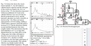
No I've never bothered. It's such a tiny amount of PFB I doubt you could hear the difference in a guitar amp either way. Here's an extract from my hifi preamps book:Thanks! Have you ever used this trick in guitar amps?
Attachments
Last edited:
I've been wondering about the bootstrapped pair since reading about it in your book...
How different would the performance be if the cathode follower was replaced with a MOSFET source follower?
The cathode follower has to drive both the positive feedback loop back to the input triode's plate and the load. They would appear to be in parallel to the cathode follower's cathode, correct?
Adding a shunt NFB loop would add yet another load in parallel.
A 12AU7 cathode follower would likely load down into this accumulated batch of loads. But it seems to me that a MOSFET source follower running at >5mA Ids should help quite a bit. No?
- Home
- Amplifiers
- Tubes / Valves
- Local CFB and bootstrap: an hybrid 12AX7 driver with 55db of gain and CF-like Zout