Since in a ccs the pot is operating like a current rheostat not a voltage divider you'd probably want to operate it towards its high resistance side not its low resistance side for the minimum amount of variability you'd need right? So a smaller fixed resistor in series to carry most of the current, then the trimmer operates in its high resistance range? I'm asking too for the very same reason. To make the decision about fixed and pot sizes, I suppose you'd first have to know what center R value you need approximately. Then choose a fixed resistor to carry most current and make the pot a higher R value that lands the variability center
somewhere in the upper range of that pot? Is there a formula that minimizes the pot current and maximizes the fixed R current, probably easy to determine in spice, which I have to learn one day.
somewhere in the upper range of that pot? Is there a formula that minimizes the pot current and maximizes the fixed R current, probably easy to determine in spice, which I have to learn one day.
I just find it extremely interesting that just a potential difference of a whopping 2.7V (maximum) would be that significant to anything?
But most of all, based on my experience with professional gear that's been absolutely being tortured (especially in the older days).
Within 15-20 years not one single unit out of many many thousands has been faulty because of a bad or drifting trimpot.
Sure I totally believe it's there, but again, I would like to see some numbers to know and understand about its significance.
Last edited:
Input in Excel with Ohms Law. Change and tweak R values and watch Current and Power change to within the safe operating areas. Buy these optimized values...

Reliability.
Pot . . . Good.
Fixed Resistor . . . Better.
All Generalizations have exceptions.
b_force,
Lucky you.
Readers of this post . . .
Have you ever experienced a pot failure over time?
Pot . . . Good.
Fixed Resistor . . . Better.
All Generalizations have exceptions.
b_force,
Lucky you.
Readers of this post . . .
Have you ever experienced a pot failure over time?
Volume pots: manyReaders of this post . . .
Have you ever experienced a pot failure over time?
Bias pots: none (I always use cermet potis (64W-housing), the wiper connected to one end of the poti)

actually a larger resistor shoukd be in parallel to carry most of the current,? So a smaller fixed resistor in series to carry most of the current, ...
when in series it just reduces the voltage and dissipation in the pot
Thousands is not about luck anymore.b_force,
Lucky you.
Regular potentiometers is a different story. But since they have an open structure, they mostly fail because of dust and other dirt. Like @planet IX mentioned.
Or with cheap ones, the wipers are gone after a while.
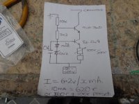
Attached is a CCS I use in all my amps. I use a zener rather than an LED as it has a higher voltage meaning you have potentially more adjustment range. I usually use a 6V2 zener, to work out the emitter resistor divide 5.4v (6V2 minus 0.6v typical Vbe) by the current you want. In the attached I needed 620r so used a 560r fixed R and a 100r Piher preset. I tend to use 500r Piher presets at present usually centered at 250r.
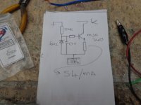
If the wiper lifting worries you use a 500r preset with two 1k fixed R's in parallel across the preset. If the wiper lifts the CCS current will be reduced. A simpler CCS also attached. MJE340's are traditionally used but a BD139 works ok too.
Andy.
If the wiper lifting worries you use a 500r preset with two 1k fixed R's in parallel across the preset. If the wiper lifts the CCS current will be reduced. A simpler CCS also attached. MJE340's are traditionally used but a BD139 works ok too.
Andy.
Attachments
The trimming potmeter for the speed setting in the Sony TC-D5M and TC-D5 PRO cassette recorders used to fail. When a reporter complained about the speed being all wrong, I had to replace it. I haven't a clue how much direct current was flowing through its wiper and in what direction.
But most of all, based on my experience with professional gear that's been absolutely being tortured (especially in the older days).
Within 15-20 years not one single unit out of many many thousands has been faulty because of a bad or drifting trimpot.
Maybe that gear was designed in accordance with the recommendations of the trimming potmeter manufacturers.
Most definitely not 😀Maybe that gear was designed in accordance with the recommendations of the trimming potmeter manufacturers.
Wondering is always a great thing! 🙂Given that wiper contact failures are intermittent, regardless of root causes like dirt or oxides from anodization, how can you be so sure that its not been a problem? Not trying to start an argument, just wondering.
I am still wondering about this whole anodization as well, or rather, the significance of it 🙂
Because I just haven't seen it being that much of a problem in practice.
Maybe with some extremely specialized and sensitive gear (think professional lab grade measurement equipment and such).
In this particular case, we knew certain test values from the schematics and production.
Many of those products were still well within spec and tolerances, sometimes after like 10 years.
We did some checks at a few to actually see if the trimpots would act erratic or weird, but they were all fine.
Again, I am talking about trimpots, just those standard blue ones (whatever brand you like).
Generic potentiometers, especially when being used often, very different story.
Trimpots that are open, are also not great.
Hi,
I'm always afraid of using small trimmers where a significant current will flow through the wiper. . . . . . .
If it hasn't already been stated : Use the trimmer to get the operating point you want, once done, measure the resistance of the trimmer , replace with fixed resistor. Easy
I think just measuring the difference in voltage as well as the current is a little bit more straightforward. 😉once done, measure the resistance of the trimmer
But whatever makes you happy.
If this is a set-it-once design, I'd use the trimmer pot to find the optimal setpoint for the circuit, remove the pot, measure its DCR, and then used a fixed resistor of that value. Kluge up a series/parallel combo if necessary to achieve the desired value, since chances are high that the setting will not conveniently fall on a standard one.Hi,
I'm always afraid of using small trimmers where a significant current will flow through the wiper. Will the following approach (U1 section) be fine for biasing a CCS using a pot? The extra resulting resistor in the current path is small enough to not affect the CCS, I believe. Any drawback of this approach?
Thank you!
Jose
View attachment 1212699
I was answering the first words of the OP's initial post. If there's a little voice of concern somewhere in the back of mind it's best to take care of it in a way that leaves no room for wondering what might happen while you're out of the room. Wipers do fail, even in circuits designed by some you'd expect would know better. And some of those in situations where failure leads to expensive consequences.I think just measuring the difference in voltage as well as the current is a little bit more straightforward. 😉
But whatever makes you happy.
Some take everything to the edge of ratings, trusting the sheet. Experience tells me it's wise to err on the conservative side where possible, especially if it means freeing your mind of needless afterthought.
I do that when I build a final amplifier. But I want to be able to change tbe current by a wide range when prototyping, without re-soldering.If it hasn't already been stated : Use the trimmer to get the operating point you want, once done, measure the resistance of the trimmer , replace with fixed resistor. Easy
Diabolical Artificer,
Whenever I use a CCS for a pair of cathodes of dual triode input/splitter/driver stage (Constant Current 'Sink', as I call it), I want a Low Burden Voltage.
My first such CCS was very close to the second schematic of your Post # 28.
I used a series resistor from a very well filtered + supply to a 1.7V LED, no bypass cap, a base stopper resistor, 2N3053 NPN, and an emitter current setting resistor.
Simple, and it worked well with the dual triode tube types I selected back then, for LTP phase splitting.
I always calculated the emitter resistor value, and wired it in. The current was Very close to what I needed . . . What pot or rheostat?
Why the 2N3053?
I had them.
Low Saturation Voltage
High Collector Impedance, Even Before using an [un-bypassed] emitter resistor, and that resistor raises the collector impedance quite significantly.
Nice intrinsic heat radiating TO-39 metal package (better in all ways for Audio CCS duty than a smaller plastic 2N3904, for example).
For Self Inverting CCS to do current sinking of a pair of triode wired beam power tubes, I used a Motorola NPN TO-220 package, and a heat sink (actually, just the aluminum chassis was good enough to use as a heat sink).
I do not build high power amplifiers.
Now I use things like LM334, etc. for the input/phase split/driver tubes. Well, now comes the darn plastic package (Ugh!).
Or, I build a Balanced Amplifier, no phase inverter needed in the tube amplifier, just an XLR input connector, and a 7 resistor input shunt attenuator and dual grid circuit.
- Home
- Amplifiers
- Tubes / Valves
- CCS biasing: Avoiding current in a potentiometer wiper