Correct you
To boot, kludgy clumsy band aids, that introduce 10 new problems for each one they "solve".
Correct your grounding/layout errors instead of searching for band-aids.I’ve built this with a conventional power supply, but nothing I do gets the hum to a reasonable level. Therefore, I’m going to try to power it with a battery. I’m not familiar with dc-dc that you refer to. I need 18 v and 108 v for the two sides of the triode at the plates and I need a filament supply.
To boot, kludgy clumsy band aids, that introduce 10 new problems for each one they "solve".

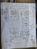
Here is the schematic. My handwriting isn't the best, but I think you should be able to read it. I'm starting to think two 60V Dewalt batteries will work the best for this, because I can just buy their charger. No need to charge the individual cells 4 at a time.
Attachments
So you are saying get a 12vdc wall wart to power both the filament and the inverter. Then there would be a b+ much like in my schematic that I could use to put power to the plates?
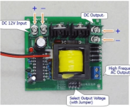
I built a pre amp using a 12 vdc 3 amp wall wart. I used an lm317 regulator for 6.3 volts and could switch to 12 for heaters It runs 6gu7 or 12au7 tubes and sounds good I used a high voltage boost convert from Amazon for 300vdc. https://www.amazon.com/gp/aw/d/B0B73RL46Q?psc=1&ref=ppx_pop_mob_b_asin_title
It worked great but I still had to filter the output of the 300 volts and ground everything. I'm not sure if you can get enough current for a power tube
It worked great but I still had to filter the output of the 300 volts and ground everything. I'm not sure if you can get enough current for a power tube
Correct.So you are saying get a 12vdc wall wart to power both the filament and the inverter. Then there would be a b+ much like in my schematic that I could use to put power to the plates?
I’m not sure how I would regulate down to 6.3 or 12.6 VDC from 120vdc. That’s too high of an input voltage for the lm317.
Now you see why this battery idea isn’t so great. The original design could be a very simple fix. Short of designing custom switching power supplies you aren’t going to make this work with arbitrary battery voltages. Look up ohms law in regards to dropping 48 volts to power a 12AX7. Most of your power will be wasted in heat.
Way back when batteries were used to power radios, it seems that they had different strings for just such a case. Man, it must have been a real pain to use what was available back in the day. For a time, it seems that some of the battery cells were wet, but of course they had their own problems.
Even the very first telephones had battery power supplied at the house, but that soon changed, when the central office supplied DC voltage over the line.
Batteries were used because there were no other real options at the time.
Even the very first telephones had battery power supplied at the house, but that soon changed, when the central office supplied DC voltage over the line.
Batteries were used because there were no other real options at the time.
Use a 12 VDC supply, Regulate the 12VDC to 6.3 and use a big heat sink on the LM317. Use the converter to get 120VDC from 12 VDC. I do think this will be just as much work is troubleshooting your amp.I’m not sure how I would regulate down to 6.3 or 12.6 VDC from 120vdc. That’s too high of an input voltage for the lm317.
I’m buying one of the dc to dc converters to try with a 20v battery, and I’ll use my lantern battery for the filament. Hopefully, I won’t have any hum out of it, and I’ll be able to finish my recording project. Thanks for the advice!
I put this together, and all the hum was gone. Thank you for the advice. It actually worked this time !!!!!
When you get these working, they seem to have a special sound to them. Maybe just a lack of self made hum.
I don’t have much time right now, but I will update it when I get a chance. Basically I removed the transformer and all of the diodes. Then I hooked the lantern battery up to the filament and the 20v dewalt to b+ side. The 330k resistor I removed as well. This gives me about 22 v at the plates on one side and 108 v on the other. I will be doing some more on it to try to eliminate the lantern battery. If that works I will try the 12v wall wart, just for kicks, but I bet that will make it hum.Could you please update the schematic with your final solution?
I was also looking at the volume control being at the output instead of the input. Doesn't that run the circuit full tilt, at least by way of the input signal? And then the volume control is after all that? I have heard of this before but never seen or heard one in action. I just wonder about the possible distortion with full on input signal.
Yes there should be a ground at pin 8 between the 470k resistor and the cathode. Sorry about that!! The pot is wired just the same way that Bogen wired theirs in the MX60A.
It’s a grid leak bias circuit. Maybe that explains it. I don’t know. The volume control works very well, and if you turn it all the way up you get some pretty good tube saturation, which can be used with the attenuation on a DI for a good effect sometimes.I was also looking at the volume control being at the output instead of the input. Doesn't that run the circuit full tilt, at least by way of the input signal? And then the volume control is after all that? I have heard of this before but never seen or heard one in action. I just wonder about the possible distortion with full on input signal.
- Home
- Amplifiers
- Tubes / Valves
- Battery powering 12AX7