Can anyone post measured Gm and Mu for one of the Mullard Re-Issue 12AT7? It might give some insight into what is going on. I would suspect Gm and possibly Mu are below true 12AT7 specs. Lo Gm with low value anode and cathod resistors in the cathodine could cause a low Gm tube to go into positive grid condition.
Put a test signal through the amp and measure the output voltage (across the speaker or load) ... The level at the output should drop noticeably when the negative feedback is connected .... If the level increases when the feedback is connected you need to swap the primary wires.
Excellent thank you George. The genius of simplicity! Half a volt of 1kHz sine wave going in gave 0.6V AC out, with FB and 0.9V, without FB - both channels. So I know my phasing is correct. Don't let this go to your head but ... you are the man! ;-)
Simon
In post #14 you already reported that the amp got louder without NFB connected.
So I had no doubt the OT is correctly wired.
Also oscillation caused by reversed OT leads (resulting in positive feedback) is typically an audible frequency.
But oscillation with correct wiring and NFB in place is always above the audible range.
I've seen oscillation frequencies between 40kHz and over 400kHz with tube amps.
That's why I said "use your scope".
Since OP hard-wired the amp it would be easy to try 12DT8 or 6DT8 (depending on heater supply) which are 12ATs with heater connected to pins 4&5 only. They are significantly less expensive (at least in the US) than “real NOS 12AT7s”.In Australia, this store (https://www.thevalvestore.com.au/12-12at7-ecc81) has JAN GE 12AT7WC (USA-made) for the same price as JJ version 12AT7s.
A practical suggestion thank you Francois G - but those 12DT8s and 6DT8s don't seem to be readily available in Australia.
Simon
Simon
If you take DC voltage readings of the 12AT7 pins without NFB, are they different than you get with NFB?
Rongon - Thanks, I did this before and I don't think so. The voltages were not significantly different with/without FB connected - and probably well within the variability caused by B+ fluctuation that occurs at my house due to mains voltage shift during measurement. For example, for pins 1, 2, 3, 6, 7 and 8 on L/R and with 75K for R106:
.....with FB......with no FB
.......L/R..............L/R
1....193/186........192/185
2.....97/104.........98/106
3.....97/102.........99/106
6.....97/102.........99/106
7.......0/0...............0/0
8....0.78/0.74.....0.84/0.80
Perhaps more telling is that when I swapped the 12AT7s left and right, the voltages largely shifted with them - see these results which are almost a left/right swap for the 'with no FB' numbers above:
.....FB still off
.........L/R
1....184/189
2....105/100
3.....105/99
6.....105/99
7........0/0
8....0.79/0.83
Does this all tell us something?
Simon
Last edited:
Rikaro, thank you. Can I understand this a bit better?But oscillation with correct wiring and NFB in place is always above the audible range.
I've seen oscillation frequencies between 40kHz and over 400kHz with tube amps.
That's why I said "use your scope".
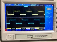
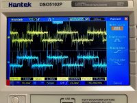
I tried sine wave inputs of 0.5V to 1.0V and 1kHz through 10kHz. The scope shows a nice sine wave output but there's a bit of variable "hair" all over it (a little fuzzy rather than clean line). I took pictures of left and right output traces at 1kHz and 1v input.
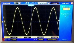
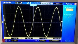
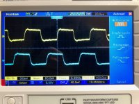
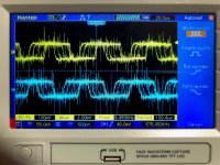
There was also some flicking to the opposite phase on some settings - mostly lower volume settings (but I'm hoping this was just the triggering on the scope?). A third picture below shows the trace flicking across to the inverted phase (note: the inverted phase does not appear to show at the same time as the main phase, it's just a flicker that the camera exposure caught, and using the Run Stop button only show the original phase or the invert, not both).
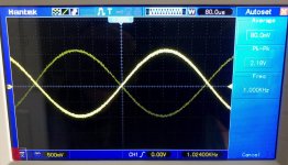
Would you be able to suggest the next tests for further diagnosis and to look for oscillation? I'm a scope newbie.
many thanks
Simon
Hi Rikaro, or others,
So I fed sine waves into both channels and connected my multimeters to the channel outputs. I verified that these meters reliably and accurately read the frequency of the sine wave output, by comparing the measured output frequency vs the input, right up to 500 kHz. I also verified that the meters reliably and (reasonably) accurately reflected the amplitude of the output, by observing the measured AC outputs as I varied the input signals from 0V to 1.2V.
Then with no input (with first open and then with shorted inputs) I noted zero readings for AC voltage and zero readings for Hz on the outputs.
Does this suggest I have no oscillation, at least with the amp as so tested?
Simon
Thanks, too, tikaroo, for your suggestion yesterday. I'm still trying to digest and understand how it works, so please accept this as a holding response for the moment. But meanwhile, is it easily explained why increasing the two load resistances and reducing the current makes the bias more negative?Rather than increasing R106 (which changes gain and reduces Vk in the first stage) you could increase R107 and R108 to decrease the phase splitter current and make the bias more negative.
Simon
Does your signal generator have square wave capability? If so, can you capture what a square wave looks like at 1kHz and 10kHz with 10mV and 100mV input? That's a test that should reveal high frequency oscillations, which might look like wavy squiggles riding on the horizontal parts of the trace, or as sharp spikes (overshoot) on the leading edges. You want to see nice, clean right angles on the square wave,
Your DMM might be able to measure frequency up to 500kHz, but that doesn't mean it can measure AC voltage at such frequency.Hi Rikaro, or others,
So I fed sine waves into both channels and connected my multimeters to the channel outputs. I verified that these meters reliably and accurately read the frequency of the sine wave output, by comparing the measured output frequency vs the input, right up to 500 kHz. I also verified that the meters reliably and (reasonably) accurately reflected the amplitude of the output, by observing the measured AC outputs as I varied the input signals from 0V to 1.2V.
Simon
Even good professional meters like the Fluke 87V measure AC voltage only up to 20kHz with good accuracy.
Your scope pics don't show any typical signs of HF oscillation.
(What I do see is somewhat noisy signals and scope artefacts due to unstable triggering.)
What load did you use, speaker or resistor?
Also tube DC voltages didn't change significantly without NFB.
So it seems I was wrong suspecting oscillation.
I think the reported variations between different 12AT7s can plausibly explain the biasing issue.
Thank you Rikaro - I used speakers to load the amp. (I had read that speakers may be a necessary load for some forms of oscillation.)What load did you use, speaker or resistor?
My summary and some remarks:
- The reported positve Vgk means grid current, which is a bad thing as it causes/increases distortion.
- With grid current the grid signal modulates the grid input impedance resulting in distortion.
- A 12AT7 which corresponds to its datasheet should have a Vgk of -0.8V at Vak = 100V and Ik = 4mA.
- Positive Vgk means that the tube is running out of current leaving its linear range, so that the cathode voltage no longer correctly follows the grid voltage.
- The PI circuit here is quite demanding wrt high current and low Vak. Both conditions are known to facilitate grid current. Nevertheless a „real“ 12AT7 should work fine with the original circuit.
- Countermeasures with existing tube(s): 1) Increasing the plate resistor of the gain stage lowers its plate voltage and the cathode current of the PI. This in turn increases the Vak of the PI triode. Both effects help to get back to linear operation.
- 2) Increasing plate and cathode resistors of the PI lowers PI current which can also work.
Last edited:
Rikaro - thank you for taking the time to review my test results and offer your observations and suggestions.
I understand your countermeasure 1 to be increasing the value of R106, something I have already experimented with (although my increasing from 75K to 150K may have been too much and upset other voltage balances!). And countermeasure 2 is something that tikaroo also suggested, so that is something for me to try (and better understand how lower current makes the grid bias more negative). I will be trying to understand the impact of each of these, so maybe I should spend some time learning to use a sim.
Along with guidance from George at Tubelab, rongon, FrancoisG, jcalvarez, tikiroo and others, your inputs transform a troublesome journey into a challenge and pleasure.
I have also ordered a set of 4 USA-made NOS Philips ECG JAN 12AT7WC Tubes to try as well (thanks rongon), using the stock schematic. It will take some time, but I will report back anon.
Another thought I had was whether I could insert a coupling cap between pin 6 and pin 2 to DC isolate the PI's grid from the driver plate, and set up a separate circuit to bias the PI's grid (but then maybe it's no longer an SPP)?
Thank-you!
🙂
Simon
Direct-coupling the input voltage amplifier stage to the phase splitter stage with only around 300V B+ available is challenging. I'm generally afraid of designing for grid bias below -1.2V or so, due to variable tube characteristics. Seeing a grid bias of -0.8V scares me. It's probably an irrational fear, but I have it. Also what Rikaro wrote about grid current causing distortion is true, so that is a concern.
In simulation (which you can't always trust for fine-edged decisions like this) I found that making R106 = 100k and increasing the value of the phase splitter load resistors from 24k up to 27k gets the grid bias farther away from 0V. With those changes in place, LTspice sees -0.8V Vg-k on the phase splitter using Adrian Immler's Electro-Harmonix (Russian) 12AT7 model.
If you do go the route of placing a coupling cap between pins 6 and 2 of the 12AT7, you'll also need to arrange a way to correctly bias the phase splitter stage. That's usually done with cathode bias, but you can also use a voltage divider to employ fixed bias. A good explanation of this is here: http://www.valvewizard.co.uk/cathodyne.html
In simulation (which you can't always trust for fine-edged decisions like this) I found that making R106 = 100k and increasing the value of the phase splitter load resistors from 24k up to 27k gets the grid bias farther away from 0V. With those changes in place, LTspice sees -0.8V Vg-k on the phase splitter using Adrian Immler's Electro-Harmonix (Russian) 12AT7 model.
Yes, that would be a redesign, but if that's what it takes to get your amp working with the materials you have at hand, then that's what it takes. Hopefully using American 12AT7s will work out for you.I could insert a coupling cap between pin 6 and pin 2 to DC isolate the PI's grid from the driver plate, and set up a separate circuit to bias the PI's grid (but then maybe it's no longer an SPP)?
If you do go the route of placing a coupling cap between pins 6 and 2 of the 12AT7, you'll also need to arrange a way to correctly bias the phase splitter stage. That's usually done with cathode bias, but you can also use a voltage divider to employ fixed bias. A good explanation of this is here: http://www.valvewizard.co.uk/cathodyne.html
Last edited:
No need to eliminate the direct coupled circuit , maybe Tubelab or others can give you the actual voltages so you could tweak your components for those values . Or simply buy tubes that are known to work OK in those conditionsRikaro - thank you for taking the time to review my test results and offer your observations and suggestions.
I understand your countermeasure 1 to be increasing the value of R106, something I have already experimented with (although my increasing from 75K to 150K may have been too much and upset other voltage balances!). And countermeasure 2 is something that tikaroo also suggested, so that is something for me to try (and better understand how lower current makes the grid bias more negative). I will be trying to understand the impact of each of these, so maybe I should spend some time learning to use a sim.
Along with guidance from George at Tubelab, rongon, FrancoisG, jcalvarez, tikiroo and others, your inputs transform a troublesome journey into a challenge and pleasure.
I have also ordered a set of 4 USA-made NOS Philips ECG JAN 12AT7WC Tubes to try as well (thanks rongon), using the stock schematic. It will take some time, but I will report back anon.
Another thought I had was whether I could insert a coupling cap between pin 6 and pin 2 to DC isolate the PI's grid from the driver plate, and set up a separate circuit to bias the PI's grid (but then maybe it's no longer an SPP)?
Thank-you!
🙂
Simon
- Home
- Amplifiers
- Tubes / Valves
- Tubelab SPP - Bias of 12AT7 Phase Splitter?
