
I got the AHCT from Mouser and the HCT from ebay, it would be nice to hear from someone who uses the AHCT with the AD1862. 🙂
Now that the AD1862s have arrived, I might build that last DAC. 😎
Now that the AD1862s have arrived, I might build that last DAC. 😎
Last edited:
I am concerned if the faster AHCT will not cause audible problems in higher sampling rates (like 96 or 192 kHz), so ask for this test 😉
Attachments
I was able to get the 74HCT164E to work with the AD1862.
Does anyone knows the AD1862 power up sequence, which supplies much turn on first.
I don't know why but my L7905CV always fails to start at first attempt and I get -0.7 V in +Vd pins of the AD1862s, I have to restart the supplies several times to get about +4.95 V. What can be the problem?
Does anyone knows the AD1862 power up sequence, which supplies much turn on first.
I don't know why but my L7905CV always fails to start at first attempt and I get -0.7 V in +Vd pins of the AD1862s, I have to restart the supplies several times to get about +4.95 V. What can be the problem?
You should have more than enough start load (-5mv minimum) with led, so there should not be an issue there.
But make sure you are using the correct regulator for +V, as 7905 is -V regulator. I don't know how you are getting +5V with it 😅
But make sure you are using the correct regulator for +V, as 7905 is -V regulator. I don't know how you are getting +5V with it 😅
Sorry, I said L7905CV but instead I should have said L7805CV 😋, my mistake.
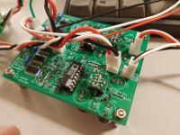
This circuit is not Miro's board neither a custom board it is a breadboard prototype, the only load at the 5V regulator outputs are the 100 nF capacitor, the filter/reservoir capacitors and the AD1862s' +Vd pin.
When it works it sounds pretty good, I am using an AD811 I/V stage.
This circuit is not Miro's board neither a custom board it is a breadboard prototype, the only load at the 5V regulator outputs are the 100 nF capacitor, the filter/reservoir capacitors and the AD1862s' +Vd pin.
When it works it sounds pretty good, I am using an AD811 I/V stage.
Add 330R resistor and red led. It should provide enough of a load for it to work properly.
Quick drawing on phone according to your circuit description.

Quick drawing on phone according to your circuit description.
@danny92 Do the load with LED suggested by Brijac for all regulators 🙂
What is the regulator brand and where it was bought? (onsemi brand is very good) I have never experienced a 7805 controller in my life, that refused to start. What is the reservoir capacitor type? I strictly do not recommend using tantalum capacitors after regulator (one dangerously exploded in my setup from an unknown reason).
What is the regulator brand and where it was bought? (onsemi brand is very good) I have never experienced a 7805 controller in my life, that refused to start. What is the reservoir capacitor type? I strictly do not recommend using tantalum capacitors after regulator (one dangerously exploded in my setup from an unknown reason).
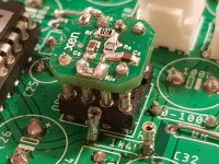
Thank you very much @Brijac and @miro1360, the LED worked like a charm, I have now a solid 4.97 V at +Vd of both AD1862s.
I only have this LED the other regulators don't have any LED. With the power supply I am currently using 4x9V NiMH 320mAh batteries the consumption would be two high I guess but I could try to add them.
The negative regulators are similar but have a 1 uF tantalum capacitor (Vishay) at their outputs, is it a bad practice?
I only have this LED the other regulators don't have any LED. With the power supply I am currently using 4x9V NiMH 320mAh batteries the consumption would be two high I guess but I could try to add them.
Positive regulators only have 100 uF (analog) and 10 uF (digital) electrolytic capacitors, close to the AD1862s pin, the filters are 100 nF close to the regulator output pin and also close to the AD1862s pins.What is the reservoir capacitor type? I strictly do not recommend using tantalum capacitors after regulator (one dangerously exploded in my setup from an unknown reason).
The negative regulators are similar but have a 1 uF tantalum capacitor (Vishay) at their outputs, is it a bad practice?
It is a L7805CV from ST I bought it with other components from DigiKey.What is the regulator brand and where it was bought?
Great! Glad to have worked, and not being a faulty regulator. I've read somewhere before that some 78xx and 79xx regs require close by 5ma load. Reading st datasheet confirmed it. "Note: Minimum load current for regulation is 5 mA". That led shouldn't drain your battery much, and if other regulators are doing fine, you can skip it and reduce consumption.
L7805CV is not LDO regulator ,so for 5V on the output should have 6,5V on the input , not so good for batteriesIt is a L7805CV from ST I bought it with other components from DigiKey.
LDO would be much better, my choice would be ADP7118 and ADP7128
- Home
- Source & Line
- Digital Line Level
- DAC AD1862: Almost THT, I2S input, NOS, R-2R