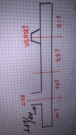
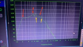
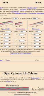
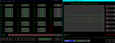
If I put a stub in a 300cm TL as L12(100cm) and add the stub as L45(60cm), I get rid of the second and third resonances (300/3 and 300/5 shown as red arrows.
but what are the new yellow resonances created (by adding the 60 cm stub at the end? )
but what are the new yellow resonances created (by adding the 60 cm stub at the end? )
Attachments
Last edited:
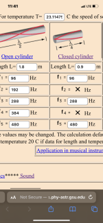
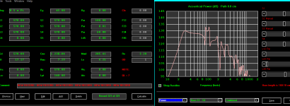
I suppose they are related to the ‘~360cm overall length created by the 60 cm stub?
?360/ 4 is 90 cm, close to the ~96hz peak ? And 192 hz (45cm)?
?360/ 4 is 90 cm, close to the ~96hz peak ? And 192 hz (45cm)?
Maybe I’m retarded ?
the 300/100/60 cm resonances are irrelevant because of the actual 360 cm total pipe Length and I’m chasing my tale😝
the 300/100/60 cm resonances are irrelevant because of the actual 360 cm total pipe Length and I’m chasing my tale😝
Attachments
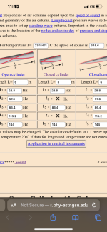
Maybe this is better? I offset the driver at the second resonance(100cm) and I offset the exit at the third(60cm)?
still have those ‘new’ resonances at ~75, 50cm, etc and this 300cm long??
even numbered harmonics of the entire 300cm with closed ends maybe?
still have those ‘new’ resonances at ~75, 50cm, etc and this 300cm long??
even numbered harmonics of the entire 300cm with closed ends maybe?
Attachments
Last edited:
anyone able to breakdown the different responses created in these ?
thers an issue at 72 hz/120cm now?
thers an issue at 72 hz/120cm now?
Attachments

Last edited:

No clue w/o HR file, though my knee-jerk response is: I noted corner loading, so does changing pi loading shift them away from basic textbook calcs?
Maybe try to make it "stick out" more by testing the concept with unrealistically magnified lengths (but same ratios of interest).

Yes, slightly. My laptop took a sh!t or I’d post the txt file … 🫤No clue w/o HR file, though my knee-jerk response is: I noted corner loading, so does changing pi loading shift them away from basic textbook calcs?
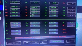
ID = 54.10
Comment = NEW RECORD - NEW RECORD - NEW RECORD - NEW RECORD - NEW RECORD - NEW RECORD
|RADIATION, SOURCE AND MOUTH PARAMETER VALUES:
Ang = 2.0 x Pi
Eg = 45.00
Rg = 0.00
Clo = 0.00
|HORN PARAMETER VALUES:
S1 = 570.00
S2 = 570.00
Par = 60.00
F12 = 0.00
S2 = 570.00
S3 = 570.00
Par = 0.01
F23 = 0.00
S3 = 570.00
S4 = 570.00
Par = 100.00
F34 = 0.00
S4 = 0.00
S5 = 0.00
L45 = 0.00
F45 = 0.00
|TRADITIONAL DRIVER PARAMETER VALUES:
Sd = 570.00
Bl = 17.17
Cms = 1.23E-04
Rms = 7.29
Mmd = 285.41
Le = 4.25
Re = 3.20
OD = 1
|ADVANCED DRIVER PARAMETER VALUES FOR SEMI-INDUCTANCE MODEL:
Re' = 0.00
Leb = 0.00
Le = 0.00
Ke = 0.00
Rss = 0.00
|ADVANCED DRIVER PARAMETER VALUES FOR FREQUENCY-DEPENDENT DAMPING MODEL:
Rms = 0.00
Ams = 0.00
|PASSIVE RADIATOR PARAMETER VALUE:
Added Mass = 0.00
|CHAMBER PARAMETER VALUES:
Vrc = 0.00
Lrc = 0.00
Ap = 570.00
Lpt = 140.00
Vtc = 0.00
Atc = 0.00
Acoustic Path Length = 0.0
|MAXIMUM SPL PARAMETER VALUES:
Pamp = 100
Vamp = 25
Iamp = 4
Pmax = 600
Xmax = 15.2
Maximum SPL Setting = 3
|ABSORBENT FILLING MATERIAL PARAMETER VALUES:
Fr1 = 0.00
Fr2 = 0.00
Fr3 = 0.00
Fr4 = 0.00
Tal1 = 100
Tal2 = 100
Tal3 = 100
Tal4 = 100
|ACTIVE BAND PASS FILTER PARAMETER VALUES:
High Pass Frequency = 0
High Pass Slope = 1
Low Pass Frequency = 0
Low Pass Slope = 1
Butterworth High Pass Order = 1
Butterworth Low Pass Order = 1
Linkwitz-Riley High Pass Order = 2
Linkwitz-Riley Low Pass Order = 2
Bessel High Pass Order = 1
Bessel Low Pass Order = 1
2nd Order High Pass Q = 0.5
2nd Order Low Pass Q = 0.5
4th Order High Pass Q = 0.5
4th Order Low Pass Q = 0.5
Active Filter Alignment = 1
Active Filter On / Off Switch = 1
|PASSIVE FILTER PARAMETER VALUES:
Series / Parallel 1 = S
Series / Parallel 2 = S
Series / Parallel 3 = S
Series / Parallel 4 = S
|EQUALISER FILTER PARAMETER VALUES:
Band 1 Frequency = 0
Band 1 Q Factor = 0.01
Band 1 Gain = 0.0
Band 1 Type = -1
Band 2 Frequency = 0
Band 2 Q Factor = 0.01
Band 2 Gain = 0.0
Band 2 Type = -1
Band 3 Frequency = 0
Band 3 Q Factor = 0.01
Band 3 Gain = 0.0
Band 3 Type = -1
Band 4 Frequency = 0
Band 4 Q Factor = 0.01
Band 4 Gain = 0.0
Band 4 Type = -1
Band 5 Frequency = 0
Band 5 Q Factor = 0.01
Band 5 Gain = 0.0
Band 5 Type = -1
Band 6 Frequency = 0
Band 6 Q Factor = 0.01
Band 6 Gain = 0.0
Band 6 Type = -1
|STATUS FLAGS:
Auto Path Flag = 0
Lossy Inductance Model Flag = 0
Semi-Inductance Model Flag = 0
Damping Model Flag = 0
Closed Mouth Flag = 1
Continuous Flag = 1
|OTHER SETTINGS:
Filter Type Index = 0
Filter Input Index = 0
Filter Output Index = 0
Filter Type = 2
MEH Configuration = 0
ME Amplifier Polarity Value = 1
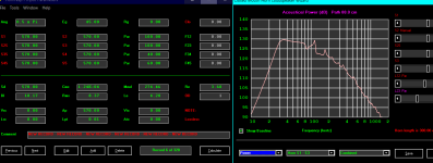
wondering what all these resonances are and what part of the ‘pipe’ they are generated from?
very intersting 😵💫
very intersting 😵💫
Attachments
Last edited:
👍 AFAIK I'm going to be busy the rest of the day doing mostly unpleasant 'things', so good 'hunting' for now...........

Nice! This seems like a great idea to spread them out further and try to decipher which resonance is coming from what section of the ‘pipe’ .Maybe try to make it "stick out" more by testing the concept with unrealistically magnified lengths (but same ratios of interest).
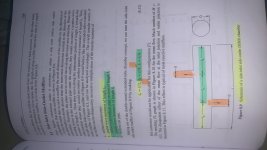
Yep. 🙂 IMO, the thing with optimizing axial/longitudinal stuff is that reality is in 3-D. I don't have time to look harder at your muffler book apparent discrepancy, but it wouldn't be the first time a book had a misprint. Maybe it's right--dunno--no time/brain for that right now. If you don't trust what HR is showing you vs. the book, stick it in Akabak to confirm, etc. Maybe that spicyTL thing does stubs too and is easier to you than Akabak. What about the old Leonard thing--is that still around? You need another tool, BW--it's time... 🙂 HR will always be your love, we know (and ours too!), but, like audio, sim tools are not monogamy and it's okay.
OK, Still a bit60 x 2 is 120 cm? This muffler reference gives 1/2 wave to the upstream stub and 1/4 wave to the downstream section and stub?
on HR's way to do these various MEHs, so view my rev with a 'jaundiced eye'. 🙄ATM no clue if this answers your original Q, but at least you'll be close assuming me n' HR are fundamentally correct.
Forgot to set QL to 'lossless' to highlight this extremely resonant pipe.
Attachments
- Home
- Loudspeakers
- Subwoofers
- Multiple stubs in QW pipes?