Also the RIAA feedback circuit - is there a way to see/calculate the frequency equalisation of the RIAA circuit?
Use a behavior voltage model (B), and insert the following into VALUE:
V=V(Out1) Laplace=(1 + 3.18e-3*s)*(1 + 7.5e-5*s)/(1 + 3.18e-4*s)
Attachments

Ok - I will have a proper look at this later = Great!Use a behavior voltage model (B), and insert the following into VALUE:
V=V(Out1) Laplace=(1 + 3.18e-3*s)*(1 + 7.5e-5*s)/(1 + 3.18e-4*s)
Lipshitz, On RIAA Equalization Networks.Also the RIAA feedback circuit - is there a way to see/calculate the frequency equalisation of the RIAA circuit?
Thanks,
Rich
(https://www.pearl-hifi.com/06_Lit_A...s/Lipschitz_Stanley/Lipshitz_on_RIAA_JAES.pdf)
A B S O R B T O T A L L Y
Lipshitz is king.
Jackinnj,
That's super helpful, (my system can't replay at 8Hz though!)
The Spice model you are using , is that possible to share I am sure my competence on Spice will not allow me to construct this!
I have ended up with R4=1K and I am considering changing the 2530pF and 750pF caps if needed (also as required R9/50 R10)
To my ears it's sounding pretty good though already.
Thanks!
Rich
If needed how? They're very carefully calculated. Not necessarily correctly calculated ;-), but carefully. Ditto the resistors they are in parallel with.construct this!
I have ended up with R4=1K and I am considering changing the 2530pF and 750pF caps if needed (also as required R9/50

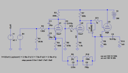
Just so I am clear on the model as it's way more complex than I could create ;-)Here;s the LTSpice file
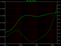
The Run to create the output voltage sweep of dB and phase against frequency are stepped for the value of R9//R50 and the output should be as flat as possible.
I am assuming the input voltage is driven by the function that represents a cartridge/RIAA defined frequency input?
Sorry if this is Spice 101 to the experts!!
Thanks, this is amazing
Rich
Any idea why the output seems to be around 57dB which on a linear voltage scale is around 715v, this seems way too high?Tweak to your heart's content. I have used a 365pF variable cap to adjust the values of the Lipshitz C1 and C2 values -- but in listening it is of little consequence. Here's an optimized sweep:
Just a quick question on the operating point of V1, following my modifications.
B+2 = 387V
R4= 1K (measured) and the voltage across = 0.91 V
V on Plate V1 = 140V
Grid on V1 = 0V
R3 = 299.6 K (measured)
So why does the quiescent current not calcualte to be the same through the anode resistor (0.82 mA) and the cathode resistor (0.91 mA) ?
What am i missing in my calculations?
Any ideas, is this related to what is going on in the feedback circuit?
So why does the quiescent current not calcualte to be the same through the anode resistor (0.82 mA) and the cathode resistor (0.91 mA) ? What am i missing in my calculations?
Any ideas, is this related to what is going on in the feedback circuit?
There is additional DC current entering the V1 cathode from the RIAA network.
This current originates from the cathode of V3, and is equal to ( Vk3 - Vk1 ) / ( R10 + R9 // R50 ).
So for the original ARC circuit the extra DC current is: ( 160V - 1.5V ) / ( 100k + 1.82M // 15M )
or ( 158.5V / 1.723M ) = 0.092mA.
Last edited:
Rayma - thanks, again great knowledge and advice.😀
So when I look at the valve operating point for V1 I guess the effective current through the tube is acoss the anode resistor = 0.82mA as there is another ~ 0.1ma coming from the feedback circuit.
So when I look at the valve operating point for V1 I guess the effective current through the tube is acoss the anode resistor = 0.82mA as there is another ~ 0.1ma coming from the feedback circuit.
Yes, there is around 10% fixed bias on the V1 tube due to the extra current from RIAA and V3.
V1 plate current is ( 390V - 170V ) / 300k = 0.733mA.
Then V1 cathode current = 0.733mA also.
Total current through R4 = ( 1.5V / 1.8k ) = 0.833mA
Current from RIAA network = 0.092mA.
These currents are all approximate because of inexact DC voltages.
V1 plate current is ( 390V - 170V ) / 300k = 0.733mA.
Then V1 cathode current = 0.733mA also.
Total current through R4 = ( 1.5V / 1.8k ) = 0.833mA
Current from RIAA network = 0.092mA.
These currents are all approximate because of inexact DC voltages.
Last edited:
Great - thanks!
Just so I am clear, if I draw the load line for the valve V1 then I use the conventional method of plate resistor current and B+ voltage, (e.g. 390V) and the mA from 390V (Plate + Cathode resistor = 1.29mA) then the operating point is the mA through the cathode reistor? (e.g. 0.833 mA above) on this load line.
Just so I am clear, if I draw the load line for the valve V1 then I use the conventional method of plate resistor current and B+ voltage, (e.g. 390V) and the mA from 390V (Plate + Cathode resistor = 1.29mA) then the operating point is the mA through the cathode reistor? (e.g. 0.833 mA above) on this load line.
- Home
- Source & Line
- Analogue Source
- RIAA preamp feedback circuit gain