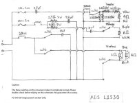
I'm trying to analyze the crossover network of ADS L1530 speakers. The schematic is posted on attached.
I calculated back the low-pass filter of the woofers, via online calculator, and found the crossover point to be around 500 Hz with Q of 0.33. This is not unusual because the active crossover, the ADS C2000 which was built for L1530, also have this characteristic in its selectable programs.
However, it's surprising that the high-pass section of the 2" midrange dome was only first-order, most ADS speakers I found usually having second-order slopes. Anyway, the problem is, as can be seen, the first-order high-pass of the midrange is formed by a single 10uF capacitor. By looking at first-order crossover table, it indicated that this filter is having crossover point at around 2.5 kHz! (with 6 Ohms midrange driver)
The question is, did I use the table or online calculator wrong, because I think there was too huge gap between the drivers -- about 5 times? I, actually, found the gap about 1.5-2.5 times in general crossover networks, but this is 5 times! What's your opinion?
Attachments
I have an assumption that is it possible that the first-order slope may have identical shape to the low-Q second-order slope?
For example, Fc = 500 Hz @ 6dB/octave equals to Fc = 500 Hz @ 12dB/octave with Q of less than 0.5.
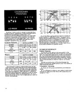
Attached is the description in the user manual of ADS C2000 active crossover module.
For example, Fc = 500 Hz @ 6dB/octave equals to Fc = 500 Hz @ 12dB/octave with Q of less than 0.5.
Attached is the description in the user manual of ADS C2000 active crossover module.
Attachments
What matters is not the electrical frequency response of the crossover itself, it is to be combined with the frequency response of the individual driver.
The 2" dome midrange has an electrical high pass filter at 1.5 kHz (10 µF with 6+4.7 ohms), so it will survive. This is assuming that the schematic is correct.
The 2" dome midrange has an electrical high pass filter at 1.5 kHz (10 µF with 6+4.7 ohms), so it will survive. This is assuming that the schematic is correct.

Nope.I have an assumption that is it possible that the first-order slope may have identical shape to the low-Q second-order slope?
I'm sorry. The schematic is incorrect. The high pass filter of the midrange isn't first order but second order. There should have a 2.6 mH inductor on it. So, the filter composes of a 10uF capacitor and a 2.6 mH inductor. This gives the result of Fc = about 1 kHz with Q = 0.33.
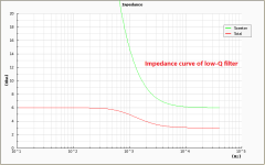
This is interesting that the low- and high-pass filters have corner frequencies at 500 and 1,000 Hz, respectively, and both have the same Q of 0.33.
The gap is now in a normal range; 2 times, that I often found in many crossovers. But, a little strange point is Q of 0.33 is too low, I think.
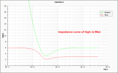
I've tried a simulation to see the behaviors of the impedance curves and discovered that the low-Q filter, here is 0.33, gives relatively high impedance at corner frequency and vice versa for the high-Q filter.
My question is, will the high impedance harm the amplifier? I won't ask for the vice versa.
This is interesting that the low- and high-pass filters have corner frequencies at 500 and 1,000 Hz, respectively, and both have the same Q of 0.33.
The gap is now in a normal range; 2 times, that I often found in many crossovers. But, a little strange point is Q of 0.33 is too low, I think.
I've tried a simulation to see the behaviors of the impedance curves and discovered that the low-Q filter, here is 0.33, gives relatively high impedance at corner frequency and vice versa for the high-Q filter.
My question is, will the high impedance harm the amplifier? I won't ask for the vice versa.
Attachments
The higher impedance is no problem. It is higher since the low Q doesn't need as much drive from the amplifier.
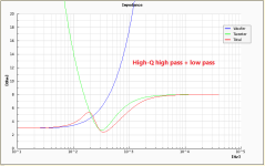
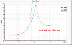
I've tried adding the low-pass filter to the system and simulate the results of two cases: low- and high-Q high-pass filters.
The results make me more confused. The high-Q when combined with low-pass filter gives flatter impedance curve, while the low-Q with low-pass provides impedance peak.
So, which one is better? Or if I can ignore the impedance peak?
PS. Impedance of drivers: woofer = 3 Ohms, tweeter = 8 Ohms
Attachments
Last edited:
As long as there are no real acoustical and electrical Measurements of each driver build in in the cabinet your thougts are only speculations without a real value. As someone here just said: not the electrical filter-curves are important but the acoustical.
Kind regards
Michael
Kind regards
Michael
- Home
- Loudspeakers
- Multi-Way
- Gap in crossover region?