Hey everyone,
I just returned from my workbench so this is a spontaneous post, I didn't prepare it very well. I'll do my homework better if this one lacks info.
Here's the thing: I'm breadboarding a tube amp. 6550 push pull pentode monoblocks.
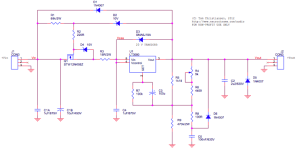
I used a 21st century Maida 300V regulator for the output tubes G2 (20 mA +/-) and the preamp (30mA).
All worked fine, got a nice voltage range on the trimpot. The input voltage is 370V.
Then I decided to go fully regulated i.e. also the output tubes plates.. Settled for 350V. The regulator had to cough up 280 mA. And it said 'no'.
Reg output drops to 325V, turning the trimpot has NO effect.
I went back to the earlier situation and it worked fine again.
Somehow the reg can't handle a few hundred mA, and I have no idea why. Could someone please shed a light on this?
Thanks!
I just returned from my workbench so this is a spontaneous post, I didn't prepare it very well. I'll do my homework better if this one lacks info.
Here's the thing: I'm breadboarding a tube amp. 6550 push pull pentode monoblocks.
I used a 21st century Maida 300V regulator for the output tubes G2 (20 mA +/-) and the preamp (30mA).
All worked fine, got a nice voltage range on the trimpot. The input voltage is 370V.
Then I decided to go fully regulated i.e. also the output tubes plates.. Settled for 350V. The regulator had to cough up 280 mA. And it said 'no'.
Reg output drops to 325V, turning the trimpot has NO effect.
I went back to the earlier situation and it worked fine again.
Somehow the reg can't handle a few hundred mA, and I have no idea why. Could someone please shed a light on this?
Thanks!
Check the input voltage. At some point it will sag too much, and the regulator will drop out.
If you are using a lab supply, check the current limiting setting.
What is your raw 370V supply?
If you are using a lab supply, check the current limiting setting.
What is your raw 370V supply?
Attachments
Last edited:
Is this one you built from one of the schematics floating around or did you buy it from me?
If you're dealing with one that you bought from me you should have no issues with 280 mA output.
I bet the issue in your case is that the input voltage droops to the point where the regulator can't regulate. Remember, the input voltage has to be at least 15 V above the output voltage at all times. This includes at the bottoms of the valleys in the ripple voltage.
Tom

Is this one you built from one of the schematics floating around or did you buy it from me?
If you're dealing with one that you bought from me you should have no issues with 280 mA output.
I bet the issue in your case is that the input voltage droops to the point where the regulator can't regulate. Remember, the input voltage has to be at least 15 V above the output voltage at all times. This includes at the bottoms of the valleys in the ripple voltage.
Hi Tom, it's a floating sxchematic 😉
I assumed (...) that the voltage margin was smaller, under full load the input voltage drops to 360V, so that's probably it. Thanks!
Raw supply is a 390 µF cap, ripple is (from the top of my head) 4V p-p.Check the input voltage. At some point it will sag too much, and the regulator will drop out.
If you are using a lab supply, check the current limiting setting.
What is your raw 370V supply?
I'll have to set the reg voltage lower, thanks.
Use a scope to verify that the regulator won't drop out at your lowest AC line, combined with
the lowest point of the input capacitor ripple, at full load.
the lowest point of the input capacitor ripple, at full load.
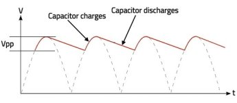
The approximate Vpp ripple, using I = C x dV/dT for the input capacitor (neglecting charging time):
Given dV/dT = I/C for the input capacitor, and assume recharging is frequent enough for a linear V decay.
If as given, I = 280mA and C = 390uF, then dV/dT = (0.28A/.00039F) = 718V/S
During the 120Hz recharging period of 8.33mS, the input voltage will drop dV = .00833S x 718V/S = 6V
So the expected Vpp ripple is roughly 6Vpp.
Attachments
Last edited:
@ Rayma, it's 100 Hz over here 😉 So that would make it 7.18V.
I'm curious, I'll measure it tonight.
I'm curious, I'll measure it tonight.
I use the same equation in my calculations, but it's still an approximation. And a crude one at that. It neglects the series resistance of the circuit which will limit the charging time. It also neglects that the load current may depend on the applied voltage which impacts the discharge time. It neglects the ESR of the capacitor. Oh, and it also assumes a zero conduction angle of the rectifier. So consider it more of a "back-of-envelope" calculation than engineering. That said, it's still useful. If it's off by a factor of two I wouldn't bat an eye. But if it's off by a factor of 10 I'd start exploring why.
To close the gap between math and reality, I recommend running a simulation with the various parasitic components factored in. PSUD II is handy for this though any SPICE simulator will do the same.
Power supply design is not an exact science. The mains voltage can vary by ±10% in countries with stable power grids and more elsewhere. Even in countries with stable power grids the voltage will have excursions beyond this ±10% range. A power transformer specified for 120 V mains and 12 V output won't deliver 12.0000000 V even if the input voltage is 120.0000 V. Both because they can't be wound to those tight tolerances but also because of the DCR of the magnet wire. Typically transformers are specified at the full rated output current, so if your circuit draws less you'll have a higher than specified output voltage. That's usually of little consequence, but it can look dramatic in tube circuits where a transformer specified for 350 V output provides, say, 385 V. "That's 35 V too much!!!" Yeah... But that's still only off by 10%.
Anyway. My point is that unregulated power supply design isn't precise enough to warrant multiple significant digits. If you can get two digits of precision you're doing well. For greater precision add a regulator on the output.
Tom
Hey folks, sorry, I accidentally shorted the regulator and completely destroyed it...
I did some measurements regarding ripple on the filter cap, here's one from only the output stage, and the next with the driver tubes also

 plugged in.
I did some measurements regarding ripple on the filter cap, here's one from only the output stage, and the next with the driver tubes also
Seems reasonable, and as expected.
Without current limiting, it's pretty much a sure thing that one will destroy such regulators on occasion.
Without current limiting, it's pretty much a sure thing that one will destroy such regulators on occasion.
Last edited:
That's one way to create fireworks. 🙂Hey folks, sorry, I accidentally shorted the regulator and completely destroyed it...
Tom
- Home
- Amplifiers
- Power Supplies
- 21st Century Maida regulator doesn't regulate heavy load.