I've made a prototype device using a PCM5102a DAC with line level output and I now want to make a PCB out of it. In this final device I'd like to have a headphone amp. For the headphone amp IC I have selected TPA6139A2
Since I'm no audio expert, I mostly went with Datasheet application notes and PCB layout guidelines. I have some doubts tho in terms of how exactly should one IC connect to the other.
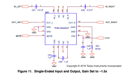
PCM5102A datasheet recommends adding a lowpass filter at the line level out (red box in the schematic). It also states that "the PCM510xA devices provide 2.1-VRMS ground centered outputs, allowing designers to eliminate DC blocking capacitors on the output".
On the other hand, TPA6139A2 application note places a 2.2uF capacitor at the input (blue box in the schematic). I figure that if the PCM5102A is ground centered, these capacitors wouldn't be necessary.
Couple of questions:
1. Is the last assumption correct?
2. Is the lowpass filter at the output of PCM5102A needed or is this intended just for an actual line out of the device?
3. If I wanted to add this headphone amp AND a line out from the device, could I just branch out from the DAC output into a line out with the lowpass filter and the headphone amp IC? TPA6139A2 input impedance goes from 10kOhm to 55kOhm depending on gain setting. I figure having both the line out and the amp in parallel would still be a high enough impedance to be easily driven by the DAC (datasheet states DAC can drive a 1KOhm load)
Cheers
Since I'm no audio expert, I mostly went with Datasheet application notes and PCB layout guidelines. I have some doubts tho in terms of how exactly should one IC connect to the other.
PCM5102A datasheet recommends adding a lowpass filter at the line level out (red box in the schematic). It also states that "the PCM510xA devices provide 2.1-VRMS ground centered outputs, allowing designers to eliminate DC blocking capacitors on the output".
On the other hand, TPA6139A2 application note places a 2.2uF capacitor at the input (blue box in the schematic). I figure that if the PCM5102A is ground centered, these capacitors wouldn't be necessary.
Couple of questions:
1. Is the last assumption correct?
2. Is the lowpass filter at the output of PCM5102A needed or is this intended just for an actual line out of the device?
3. If I wanted to add this headphone amp AND a line out from the device, could I just branch out from the DAC output into a line out with the lowpass filter and the headphone amp IC? TPA6139A2 input impedance goes from 10kOhm to 55kOhm depending on gain setting. I figure having both the line out and the amp in parallel would still be a high enough impedance to be easily driven by the DAC (datasheet states DAC can drive a 1KOhm load)
Cheers
Attachments

If serious comments and advice are wanted on this, then the project might be better served if you could show the whole schematic, indicate polarized caps on the schematic with a + mark, provide a BOM, along with the PCB layout including all layers. Any external power supplies or other devices and their layout in relation to the dac board can also be important. Otherwise you may not even be asking the right first-order questions. The above is not intended to be insulting or rude at all, its just DACs can be a lot harder go get good sound out of than someone might tend to think if they are not already very experienced in that area.
Maybe I should have clarified the overall project. The project is not a DAC, but a CPU based digital device with an analog audio output section which is essentially what I shared. The only interconnect between the digital section and the analog one are the 3 i2s signals (DIN, BCK and LRCK).
You're right about caps polarization, missed that. The two circuits I'm connecting together come from the datasheets:
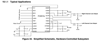
pcm5102a
tpa6139a2
(Attaching the typical application circuits for convenience)
I'd love the overall project to be reviewed and looked into and I might take that offer later, once my overall design is ready, but I didn't know how much is too much to ask 🙂. On the other hand, at this point I have this particular doubt in terms of the overall circuit which I'd like to clarify in order to move forward.
I'll try to cleanup a bit the overall schematic and post later.
You're right about caps polarization, missed that. The two circuits I'm connecting together come from the datasheets:
pcm5102a
tpa6139a2
(Attaching the typical application circuits for convenience)
I'd love the overall project to be reviewed and looked into and I might take that offer later, once my overall design is ready, but I didn't know how much is too much to ask 🙂. On the other hand, at this point I have this particular doubt in terms of the overall circuit which I'd like to clarify in order to move forward.
I'll try to cleanup a bit the overall schematic and post later.
Attachments
On the other hand, TPA6139A2 application note places a 2.2uF capacitor at the input (blue box in the schematic). I figure that if the PCM5102A is ground centered, these capacitors wouldn't be necessary.
Couple of questions:
1. Is the last assumption correct?
The datasheet says something like that AC coupling capacitors are required to block the DC voltage from the source and to prevent amplification of the TPA6139's own offset. I guess it will work, at least the recommended input voltage range includes negative voltages, but with increased output offset.
2. Is the lowpass filter at the output of PCM5102A needed or is this intended just for an actual line out of the device?
There is too little information in the datasheet for a definitive answer, but it could be needed.
The DAC output spectrum is pretty clean up to 300 kHz, I haven't found any data about what happens above 300 kHz (except a claim that it is 20 dB lower than the unspecified out-of-band noise of some unmentioned other device between 100 kHz and 3 MHz). Chances are that the filter is meant to suppress shaped quantization noise far above 300 kHz so it can't cause intermodulation products in the audio band in whatever is connected to the DAC output (such as your headphone amplifier).
3. If I wanted to add this headphone amp AND a line out from the device, could I just branch out from the DAC output into a line out with the lowpass filter and the headphone amp IC? TPA6139A2 input impedance goes from 10kOhm to 55kOhm depending on gain setting. I figure having both the line out and the amp in parallel would still be a high enough impedance to be easily driven by the DAC (datasheet states DAC can drive a 1KOhm load)
Cheers
Yes, although you could get excessive distortion when one load is switched off and the other remains active. Inputs of switched off equipment can sometimes be quite nonlinear.
Do you think it's a pointless thing to do? I figured it's better to just avoid a capacitor in the signal path if there is (in theory) nothing to filter anyway, but maybe it's not worth it for the risk of worsening some other metric.I guess it will work, at least the recommended input voltage range includes negative voltages, but with increased output offset.
That's very interesting to know. would the ideal solution be to add an additional line driver (or equivalent discrete circuit)?, something like TI DRV612 maybe?Yes, although you could get excessive distortion when one load is switched off and the other remains active. Inputs of switched off equipment can sometimes be quite nonlinear.
The minimalistic/puristic audiophile solution would be to either disconnect equipment that is off or to always have both loads turned on. If that's unpractical, a buffer is a good solution.
Its common to find small signal relays in higher quality audio gear to perform switching functions. Omron is a good brand, as is Panasonic. The proper contact material for the particular use is also important. For low level up through line level audio signals contact material such as 'Ag (Au-Alloy contact)' is good. Au is gold, and Ag is silver. Gold over silver is very good for most low level, low current signals.
- Home
- Source & Line
- Digital Line Level
- Connecting headphone amp IC into DAC IC doubts