Dear All
I am new here and new to electronics. I have this amplifier - 3 flashes in protection mode, immediately after the relays click at power on.
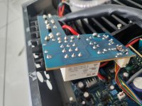
I have cleaned all the hardened brown adhesive off it.
I have also read this (great) posting here which describes checking R42 and R48. These seem to measure fine. Not shorted, not open and within 10% of what they should be.
I also saw a post from somebody who had the same issue and the power relays were his problem, so I bought a couple (for pennies) and soldered onto a circuit board for the first time in my life! Didn't fix it.
I have searched the PCBs (both sides) and components for signs of scorching, or blown out capacitors. I also cleaned off loads of gungy adhesive from between the protection circuit risers where some foam was once adhered.
I have a 540a v2 service manual and have started to go through the resistors one by one to try and find the issue. So far, nothing.
Attached to this post are some photos and I would be really very grateful if somebody who understands how these things actually work, could point me in the right direction next.
Many thanks
Ross
I am new here and new to electronics. I have this amplifier - 3 flashes in protection mode, immediately after the relays click at power on.
I have cleaned all the hardened brown adhesive off it.
I have also read this (great) posting here which describes checking R42 and R48. These seem to measure fine. Not shorted, not open and within 10% of what they should be.
I also saw a post from somebody who had the same issue and the power relays were his problem, so I bought a couple (for pennies) and soldered onto a circuit board for the first time in my life! Didn't fix it.
I have searched the PCBs (both sides) and components for signs of scorching, or blown out capacitors. I also cleaned off loads of gungy adhesive from between the protection circuit risers where some foam was once adhered.
I have a 540a v2 service manual and have started to go through the resistors one by one to try and find the issue. So far, nothing.
Attached to this post are some photos and I would be really very grateful if somebody who understands how these things actually work, could point me in the right direction next.
Many thanks
Ross
Attachments

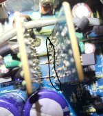
If you want to check the gungy adhesive corrosion problem
please check the gungy adhesive around the capacitors area, in below diagram we find a resistor(in red color) covered by adhesive which may be corroded the resistor to open circuit
you check all the components which covered by the gungy adhesive, clean up the old adhesive first and check each involved component ok or not
Attachments


I suggest measuring DC voltage at speaker terminals as quickest insight to amp status; ideally, it should be 0V on both channels. Does owner manual offer explanation about 3 flashes?
Hello PatrickIf you want to check the gungy adhesive corrosion problem
please check the gungy adhesive around the capacitors area, in below diagram we find a resistor(in red color) covered by adhesive which may be corroded the resistor to open circuit
you check all the components which covered by the gungy adhesive, clean up the old adhesive first and check each involved component ok or not
Your post made me go back and check that I had removed all of the brown adhesive.... And, right at the bottom of one of the risers, where they meet the main PCB, there was a line of solidified adhesive bridging all 8 pins. I cleaned it off pretty roughly and powered the amp up... Wow, amplifier powers up and now the 3 flashes are replaced by a single flash.
If I power the amp on and hold down an input button, the blue lights on top of the input buttons flash in sequence forwards, then backwards and then, when the button is released, the protection light continues its single flash.
Am I correct in thinking that holding down the button overrides the protection and provides an opportunity to set bias?
Thanks again for walking the "newbie" though this.
Ross
Attachments
And it's probably bad form to post a reply to myself, but it might be useful for somebody else if I document this 'journey'. Especially for others, like me, who have never repaired anything electronic in their life before.
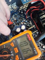
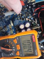
So I went and found a better (cheap) multi-meter. Looked in the 540a V2 manual and found some resistors that are the same value as the one that so many other posts suggest to suspect - R42 - just to be sure that I know how to measure resistance and that I am interpreting the results properly.
R22 - 100 kOhms - check
R2 - 100 kOhms - check
R42 - 23 MOhms - definitely NOT check
Will look online and buy a (cheap) resistor - then have a go and soldering it onto the board.
Will post the results - maybe somebody will be interested.
Ross
Attachments

Hello BSST
Thanks for the response.
I have page 20 of the 540A V2 manual here - p20 is better for me because its a "picture" of the board which I can relate to and not a circuit diagram (which means nothing to me). The page is entitled - AP17657/1 Front Panel & Mains PCB Layout (Top Side). I daren't paste a copy here (copyright).
I don't see RO or LO anywhere.
Ross
Hi Ross,
LO is at the junction of R69 and R52 near the output transistors, and there’s the analogous RO in the other channel. I imagine they are Left Output and Right Output.
I found the service manual on line at ManualsLib.com, so I think the copyright issue has already sailed…
Steve
LO is at the junction of R69 and R52 near the output transistors, and there’s the analogous RO in the other channel. I imagine they are Left Output and Right Output.
I found the service manual on line at ManualsLib.com, so I think the copyright issue has already sailed…
Steve
Replaced R42. Now when I switch on the amp, the transformer quietly buzzes for about a second and the protection circuit kicks in again. Back to three flashes. Overload.
So I try to override the protection by holding the standby button and and something, in the area of R113 starts smoking... So I am off the power button pretty fast.
@BSST - I have a 640A V2 (so am using the 540A V2 manual)...
So I try to override the protection by holding the standby button and and something, in the area of R113 starts smoking... So I am off the power button pretty fast.
@BSST - I have a 640A V2 (so am using the 540A V2 manual)...
- Home
- Amplifiers
- Solid State
- Cambridge Azure 640a V2 - 3 Flashes