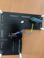
I did connect multimeter to spdif signal pin and gnd - on dsp side and there is 2.6V.. is that what you meant?Sometimes just far easier and less time consuming to just try it or at least connect a DMM and check for DC.
Before that I tried:
CSR(spdif out pin)---0.1uF -- 75ohm-->DSP(spdif in pin)
No sound at all
CSR(spdif out pin)---1.7kOhm-->DSP(spdif in pin)
As before, noise raising after time
(They didnt have 1k or 2k.. 1.7k was closest they had local shop)
Last edited:
If that was with nothing connected to the DSP pin except the meter, then yes, seems a bit high though. Try a small film cap in series with the DSP SPDIF pin if you have one at hand.did connect multimeter to spdif signal pin and gnd - on dsp side and there is 2.6V.. is that what you meant?
Yes, nothing connected, should I try measure with csr connected?
Did try ceramic cap
CSR(spdif out pin)---0.1uF -- 75ohm-->DSP(spdif in pin)
no signal
or need to be film cap?
Did try ceramic cap
CSR(spdif out pin)---0.1uF -- 75ohm-->DSP(spdif in pin)
no signal
or need to be film cap?
Yes, there are standards. S/PDIF is based on IEC958 standard. However TORX176 output (or any other TOSLINK receiver output) is not S/PDIF but at logic levels defined by Vcc. For TORX176 with 5V VCC the high level is at least 2.4V and low level at most 0.4V.So torx176 output is 5v? Thought there are some standards.
This will not work unless DSP has dedicated S/PDIF input that accepts S/PDIF signals. ADSP-21489 expects 3.3V logic levels at DAI pins so any TORX receiver with 3.3V Vcc should work.Try a small film cap in series with the DSP SPDIF pin if you have one at hand.
For SPDIF output CSR8675 uses I/O pins which are at 3.3V logic levels provided the chip is powered by 3.3V. I.e. SPDIF output is not really SPDIF but similar to TOSLINK receiver output. So if you power your CSR8675 board with 3.3V it should have output that works with your DSP.
Ceramic should work and the cap should be the closest component to the DSP pin or else your creating a high pass RC filter with the 75 resistor. Also if there is a voltage mismatch you could try looking at a resistor attenuator for the spdif, I think Rane have a tech note and that should help with search terms for a working solution to at least level and impedance match.Yes, nothing connected, should I try measure with csr connected?
Did try ceramic cap
CSR(spdif out pin)---0.1uF -- 75ohm-->DSP(spdif in pin)
no signal
or need to be film cap?
If using a DC blocking cap with a Sharc chip, it looks like you may have to bias the input pin with a resistor voltage divider to put it somewhere in the middle of its range. Otherwise it may have no DC path to ground. At least that seems to be suggested by the interfacing examples already posted.
Of course, one really needs a two channel 100Mhz or faster scope for this kind of work. Just the way it is. Otherwise its kind of like flying a plane into clouds when there are no working navigation instruments and or you don't know how to use the ones that are there. If lucky maybe you will fly out of the clouds soon and everything will be fine, or maybe not...
Of course, one really needs a two channel 100Mhz or faster scope for this kind of work. Just the way it is. Otherwise its kind of like flying a plane into clouds when there are no working navigation instruments and or you don't know how to use the ones that are there. If lucky maybe you will fly out of the clouds soon and everything will be fine, or maybe not...
The SPDIF input example from ASDP-21489 eval board clearly shows that the SPDIF signal going into the DSP is LVTTL (low voltage TTL). That should be similar to output from CSR8675 or TOSLINK receiver powered by 3.3V. No DC blocking cap is needed.
I have this board exactly, description says to power it 3.6-5V. I did power it 3.3 anyway earlier today.. and earlier also, and same result as with torx - Working but noise start to grow after time. Will get 3v3 toslink also to check.. or Im missing something?For SPDIF output CSR8675 uses I/O pins which are at 3.3V logic levels provided the chip is powered by 3.3V. I.e. SPDIF output is not really SPDIF but similar to TOSLINK receiver output. So if you power your CSR8675 board with 3.3V it should have output that works with your DSP.
Need to cut the trace on pcb, or I can leave it and just add cable to spdif pin? Its correct how I draw it? (75R or 33R?)Ceramic should work and the cap should be the closest component to the DSP pin or else your creating a high pass RC filter with the 75 resistor. Also if there is a voltage mismatch you could try looking at a resistor attenuator for the spdif, I think Rane have a tech note and that should help with search terms for a working solution to at least level and impedance match.
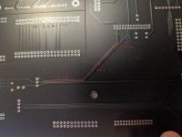
Im considering buying one, gonne need one in future anyway, so hopefully in a bit..If using a DC blocking cap with a Sharc chip, it looks like you may have to bias the input pin with a resistor voltage divider to put it somewhere in the middle of its range. Otherwise it may have no DC path to ground. At least that seems to be suggested by the interfacing examples already posted.
Of course, one really needs a two channel 100Mhz or faster scope for this kind of work. Just the way it is. Otherwise its kind of like flying a plane into clouds when there are no working navigation instruments and or you don't know how to use the ones that are there. If lucky maybe you will fly out of the clouds soon and everything will be fine, or maybe not...
Also found design for ADAU board https://www.diyaudio.com/community/threads/freedsp-octavia.393804/page-2
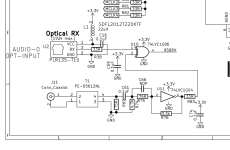
And sample application for toslink receiver used here:
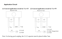
Difference from reference design 22uH(project) instead of 47uH(sample)
Added 33R close to receiver, and 33R is used for i2s/spdif
Did I miss something?
The description also states that logic level for I2S (and SPDIF) is 3.3V. So it should be powered as described (3.6-5V).I have this board exactly, description says to power it 3.6-5V. I did power it 3.3 anyway earlier today.
There is 'working' led only. I did check signastudio and there is access to decoded signal only - L/R channel, nothing before that. If it was clocking issue think there would be noise while time. Now when I power on, it works ok some time then noise start to grow. When I power off and on quick, noise is still there. If I power off and wait a bit then again its ok for some time
BTW. Is spdif clock higher than i2s? More fragile? That only this cause problemy.
BTW. Is spdif clock higher than i2s? More fragile? That only this cause problemy.
When you power it off, how long do you leave it off? Long enough for all the power supply voltages to decay? IOW what is the time delay waiting for, a voltage decay reset, thermal settling, or something else?
Also, didn't you say the SPDIF passes through an ASRC inside the DSP? If so then what are the settings for the ASRC DPLL/PLL loop bandwidth (assuming there are any)? How do you know if the ASRC remains 'locked?'
Also, didn't you say the SPDIF passes through an ASRC inside the DSP? If so then what are the settings for the ASRC DPLL/PLL loop bandwidth (assuming there are any)? How do you know if the ASRC remains 'locked?'
Hard to say, where you have marked dac, was that meant to be dsp? Thinking dsp pin to capacitor, capacitor inline, not to ground. The effect you describe is something I have experienced with an adc. A test that should work is to switch it all on, wait until the noise appears, switch all power off and short various parts of the spdif circuit to ground to dicharge any residule charge in the circuit by prodding around with a wire connected to ground. Remove the wire and power up again. If noise has gone without the waiting then likely a capacitor is slowly charging and discharging.Need to cut the trace on pcb, or I can leave it and just add cable to spdif pin? Its correct how I draw it? (75R or 33R?)
If I wait like 30sec then there is no noise, but it come back earlier, after 5 mins for example. If I power on first time that day, no noise for 30min approx.When you power it off, how long do you leave it off? Long enough for all the power supply voltages to decay? IOW what is the time delay waiting for, a voltage decay reset, thermal settling, or something else?
Also, didn't you say the SPDIF passes through an ASRC inside the DSP? If so then what are the settings for the ASRC DPLL/PLL loop bandwidth (assuming there are any)? How do you know if the ASRC remains 'locked?'
I think I did.. well dsp work @96khz, spdif is only ASRC port. I dont have access to that, sharc is different than sigmadsp. Here you have basically filters to set up. To do more you need JTAG, and they aint chaep.. other thing is you configure it in source code in VisualDSP (C language), even if I would be able to edit settings, there are is no source code for this board.
So first I would have to reverse engineer, make config for this board.. no no no no😉
SigmaDSP is different, most (if not all) settings are in sigmastudio.
Yes, what I marked dac is dps.. my bad.Hard to say, where you have marked dac, was that meant to be dsp? Thinking dsp pin to capacitor, capacitor inline, not to ground. The effect you describe is something I have experienced with an adc. A test that should work is to switch it all on, wait until the noise appears, switch all power off and short various parts of the spdif circuit to ground to dicharge any residule charge in the circuit by prodding around with a wire connected to ground. Remove the wire and power up again. If noise has gone without the waiting then likely a capacitor is slowly charging and discharging.
I tried to make it less confusing now.
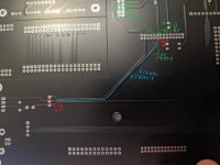
I want to add a wire(with cap and resistor) from DSP pin to CSR - green
And there is 'old' track I was using whole time - blue
After I add green wire to connect csr do I need to cut trace on pcb(blue one)"
It seems like something is discharging.. doesnt look like heat problem, dsp is barely warm, but I could spray it anyway - is liquid propane conductive?🙂
Shorting dsp signal to gnd pin will work to discharge? Or how to do it?
Suggesting a faulty cap? There was short before..
Also while I was checking sigmastudio options, I disconnected dac completely from dps for testing, also made very simple project in sigmastudio input-->VU meter-->output ..and same result I see noise on VU meter after time.
Liquid propane better not be mixed with electronics perhaps. Instead of cooling it down to see if the problem subsides, how about warming it up with a hair dryer and see if the problem emerges sooner? To freeze test chips use this spray. FreezeSpray
BINGO! I used hairdrier, like 5 seconds and theres tons of noise now. Then I did cool it with anti dust spray (good ol' propane🙂) and all ok.. did heardtier again to confirm and yeah... lots of noise
Sorry I was bit sceptical about heating problem, but I really couldnt locate any higher heat on dsp board... and still cant🙁 I did believe that if there is heating problem it will be boiling.. hmm maybe is but cant locate. Thanks everyone for help and suggestions👍and hope I can get some more🙂
So how it is? something is boiling or little heat is enough sometimes?
Any tips/trickson locating and fixing?
- Home
- Source & Line
- Digital Source
- S/PDIF input problem
