Hello Guys,
I would like to harness the forums braintrust if I may to help with a low power integrated amp. scoping .
I would like to see if it is doable , by using off the shelf diyaudio projects or other reputable boards .
So it starts like this : I would like to use the B1 korg pre-amp , since I am looking for that tubey sound (the tubier the better).
My media source should deliver around 2v peak to peak audio into the B1 .
And I would like to have around 5W RMS per channel into 8 ohms in the output .
‘So the question is what do we need to do to get B1 to 5W ? The simpler the better.
All of this : B1 preamp , power supply (linear) and the cct to get the 5W will need to fit into one nice compact box .
‘Well , relatively compact .
Much appreciate your help.
Mil

However, my experience of the Korg B1 is that it doesn't sound like valves (sorry tubes). It just sounds good.
Hello,
Thanks Guys, for your suggestions much appreciate it .
So we have basically 3 choices : ACA , ACAmini and Vfet to get the B1 to around 5W or so .
Do I understand correctly that for Vfet I need to get some Sony transistors made from unobtainium ?
Which were done in production run decades ago , and that they most likely can not be bought unless you know someone.
I guess all of these three run hefty idle currents , so I would need biggish heat sinks , for either of the three designs .
Any recommendations on the size and shape of the heat sinks ?
I have tried in the past to do a class A type 5-6W amp but ran into heat issues , even at bias current of around 1.2A .
Ended up with case I could not pickup (too hot) and a hissing noise in the audio output . So I gave up on that design.
I like the idea of those Korg tubes and am really looking forward to trying them , and if they are even a little valvey or tubey or
fire-bottley that would be a bonus.
Which design do you think would be the easiest to manage, from power and heat and size perspective?
Best Regards
mil
🙂I would like to use the B1 korg pre-amp , since I am looking for that tubey sound (the tubier the better).
I don't want to add to confusion / pile. However, getting a Korg B1 to behave (not be microphonic) is part of the consideration. Putting it into a chassis with other components adds (potentially) to that consideration.
Although it doesn't have a 'tube', I'd humbly submit the ACP+ for consideration. It's been called a "mini J2" by some. I think it has an incredible 'tube-like' character without the hassle. I doubt you would be disappointed, but the Korg B1 is a very nice choice, and I can easily see why you started there.
You sure that's not RMS? Not asking to question your statement, but to be sure. 2Vrms is a fairly common maximum output for many sources from RCA outputs. 2Vpp => 1Vp => 0V71rms. It's not hugely important since the output voltage from the source is largely dependent on the program material and the type of source. However, if you've used that figure for some back of the matchbook calculations to determine your goal of 5Wrms ... and the gain from your gear ... it becomes a bit more important.My media source should deliver around 2v peak to peak audio into the B1 .
Would you like to have that for sustained listening at 'relatively' low distortion or is that your goal for max output? The distortion of some choices starts to get above my personal comfort zones at that output. Note, that I'm comparing that to the typical distortion measurements provided at 1W. Check out some of the posted specs. Have you used any of the calculators to estimate what you may need / want?And I would like to have around 5W RMS per channel into 8 ohms in the output.
Linear PSUs negate a bit of your 'simpler the better' approach. I know this will create moaning, groaning, and gnashing of teeth... but I'd strongly consider simply using the recommended SMPSs along with a few of Mark Johnson's (or similar) filters. In general, your chassis size could be smaller, which seems to be one of your primary goals. In addition, I sincerely doubt the performance is any different unless you go to far-less-than-simple extents on the linear PSU. Making a more complex linear PSU to equal the performance of the SMPS further goes against your goals of simple and small.‘So the question is what do we need to do to get B1 to 5W ? The simpler the better.
All of this : B1 preamp , power supply (linear)
Sorry, what's a cct?and the cct
See above for balancing out some of your stated goals. Choices may need to be made.to get the 5W will need to fit into one nice compact box .
‘Well , relatively compact .
There are more, but these are a really good start.So we have basically 3 choices : ACA , ACAmini and Vfet to get the B1 to around 5W or so .
The output devices can be relatively expensive, and they are becoming harder to source. Personally, unless you know about it, must have it, and are willing to commit a larger budget, I would drop it from the list. Don't get me wrong, it meets all your criteria, but it's also going to be the largest and the most expensive, and the most difficult (IMO).Do I understand correctly that for Vfet I need to get some Sony transistors made from unobtainium ?
I recommend looking at the kits as a starting point. They all have posted dimensions. Heatsink sizes and my personal approach would differ widely based on the choice of the amplifier. But... as a starting point...I guess all of these three run hefty idle currents , so I would need biggish heat sinks , for either of the three designs .
Any recommendations on the size and shape of the heat sinks ?
VFET biggest heatsinks
ACA middle-sized heatsinks
ACA Mini has on-board heatsinks.
For the ACA Mini, you can build it on the board and plop it into a well-ventilated enclosure with no 'external' heatsinks if that appeals to you.
ACA Mini, by a long shot. You'll just want to be sure it's gonna have enough oomph.Which design do you think would be the easiest to manage, from power and heat and size perspective?
Hi vdi_nenna,
Kindest regards,
M
Could you please provide a reference, all I found was just a "regular" F4.. . . I'd say put a mini-F4 . . .
Kindest regards,
M
I am looking for that tubey sound (the tubier the better).
I associate “tubey” with tube gear that is not well designed. A really good tube preamp sounds like ‘nothing”.
dave
I think it's known as the "crippled F4".
It has the frontend input stage removed and an input transformer put in to replace the input stage (the buffer). Maybe ZM can shed some light unto it if it's even worth it with a korg preamp in front.
With such a low 5w power requirement it might be worth it.
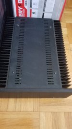
The case I used would be an example of a bit too small...
I have a 3w power follower using a 24v amps and sounds excellent. However, gets real hot in small case. In large case probably couldn't tell it's running, like my MOFO monoblocks.
https://www.diyaudio.com/community/...ass-f4-amplifier.234355/page-112#post-6397500
It has the frontend input stage removed and an input transformer put in to replace the input stage (the buffer). Maybe ZM can shed some light unto it if it's even worth it with a korg preamp in front.
With such a low 5w power requirement it might be worth it.
The case I used would be an example of a bit too small...
I have a 3w power follower using a 24v amps and sounds excellent. However, gets real hot in small case. In large case probably couldn't tell it's running, like my MOFO monoblocks.
https://www.diyaudio.com/community/...ass-f4-amplifier.234355/page-112#post-6397500
Attachments
Last edited:
crippled F4 is full F4 (all 3 pairs of mosfets in output) just sans input buffer (JFets), taking in account of having preceding stage ( preamp) with enough Cojones (low Rout) to drive it properly
now, one can use M2 sans FE stage as mini- crippled F4
just one pair of mosfets, suitable for rails from +/-15V
now, one can use M2 sans FE stage as mini- crippled F4
just one pair of mosfets, suitable for rails from +/-15V
Last edited:
Hi vdi_nenna,
Thank you for the reply, but the link shows an F4 output stage with three transistors. Do you really need that for 3W, that is about what I need.
Hi Zen Mod,
thank you for the reply.
Kindest regards,
M
I have a 3w power follower using a 24v amps and sounds excellent.
Thank you for the reply, but the link shows an F4 output stage with three transistors. Do you really need that for 3W, that is about what I need.
Hi Zen Mod,
crippled F4 is full F4 (all 3 pairs of mosfets in output) just sans input buffer (JFets),
thank you for the reply.
Kindest regards,
M
My bjt buffer sounded very much like F4, perhaps even better. And can be scaled from one output pair to full three pairs and +/_ 23 volts providing anywhere from 5 to 25 watts with no global feedback and miniscule distortion.
Put tube pre before it and you are in for sweet sound.
https://www.diyaudio.com/community/threads/output-bjts-for-buffer.386324/
Put tube pre before it and you are in for sweet sound.
https://www.diyaudio.com/community/threads/output-bjts-for-buffer.386324/
Here's my low watt power follower thread.
Easy to P2P.
https://www.diyaudio.com/community/threads/f5-article-headphone-amp.339732/
Easy to P2P.
https://www.diyaudio.com/community/threads/f5-article-headphone-amp.339732/
Hi adason,
Hi vdi_nenna,
M
I looked at your thread, thank you.My bjt buffer sounded very much like F4, . . .
Hi vdi_nenna,
thank you.Here's my low watt power follower thread.
M
Thanks Guys,
Much appreciate all of your input . It has been very helpful.
To clarify a couple points :
- I made a mistake with the output level of the source , it is indeed in rms .
To be sure I put the scope on it while playing a test tone of 1KHz wav file , recorded to max level.
And the output is 2.1V RMS or around 6V pp .
- My target is 5W RMS per channel into 8 ohms at absolute max volume (with the dial indicator at 11) when playing same 1KHz wav file .
Listening volume will be much , much less than that .
My current amp is just on 5W RMS at max , and normal listening volume is at 1/4 turn clockwise with same source .
- When I mentioned the ‘cct’ I was referring to the power amp part , and how it fits in the housing . In the context that Korg B1 and power amp cct and perhaps the power supply should fit nicely into a case .
I do agree with the suggestion to use a smps , so in that regard I have already selected the filter kit from the diyaudio store .
Depending on the space I end up with , will be whether the smps is external or internal .
As it stands , this is my short list from the diyaudio store: Korg B1 pcb and transistor kit, nutube it self, power filter kit, and ACAmini pcb and transistors kit . I will source the other bits locally to save on a big shipping bill .
What do you think ?
Regards
Mil
^ Great stuff. I think you'll have a wonderful project. A few things for clarification.
- My target is 5W RMS per channel into 8 ohms at absolute max volume (with the dial indicator at 11) when playing same 1KHz wav file .
Listening volume will be much , much less than that .
- My current amp is just on 5W RMS at max , and normal listening volume is at 1/4 turn clockwise with same source .
Depending on how the gains compare between your current system and the Korg B1 + ACA Mini, you'll likely still be ~ 1/4 turn on the volume knob or you'll drive the ACA Mini to voltage clipping.
B1K (per article) => 16dB => ~6.3x
ACA Mini => 15dB => 6x
So.... you'll have a total system gain of ~38x
5W @ 8R => ~6.3Vrms => You don't need 38x gain. tl;dr - don't turn it to 11.
A few considerations / notes - The ACA Mini has a jumper. I'd play with that to see what you like best with the B1K. As someone alluded earlier, too much 'tubey' could be too much of a good thing. YMMV. What I'd consider is taking the already potentially 'tubey' character of the ACA Mini and leaving that alone. I'd maybe combine it with a simple unity gain buffer like the B1. That lowers the total system gain to something a bit more in-line with needs and also takes out the tubey + tubey => ooey gooey potential. That's my preferences for how I might go about it. Your overall solution will turn out a wonderful project, IMO. All info provided is just FYI.
Most importantly ... enjoy the build and post pics!
- Home
- Amplifiers
- Pass Labs
- Help needed in scoping out a low power integrated amp using B1 Korg