Im struggling with spdif input on aliexpress sharc dps. All i2s in/out work fine, when I connect spdif at beginning all is fine, then noise start to raise slowly, usually takes 3-5min for noise to come. If I power off and back on quickly noise is still there. I need to wait till it 'cool down' like hour or so, then all is fine for that couple minutes when I power on.
Here is sample of how it all sounds:
https://vocaroo.com/1ePE1zNy6Wxg
i tried optical torx176, or csr8675 board.. connected with caps and coil.. or without, result is always the same. I used goldpin to connect around 10cm.. can this be cause? or something else?
Here is sample of how it all sounds:
https://vocaroo.com/1ePE1zNy6Wxg
i tried optical torx176, or csr8675 board.. connected with caps and coil.. or without, result is always the same. I used goldpin to connect around 10cm.. can this be cause? or something else?
Faulty silicon? It is AliExpress after all. Or is it just inadequately cooked and cooking itself? spdif processing might use more power - something it might be possible to measure?
Sorry if I wrote it in misleading way by 'cooling down' I meant that some time need to pass while everything is powered off to noise disappear. DSP itself don't get warm. I checked in sigmastudio and I see that noise on spdif input on vu meter.
Will post photos + screen from kikad when I can.
I don't have scope, but maybe I can measure something with multimeter?
Will post photos + screen from kikad when I can.
I don't have scope, but maybe I can measure something with multimeter?
Just gambling… please make pictures especially of the onboard voltage regulators and the used PSU.
Pictures usually say more than words. Revolutionary idea, I know. Imagine calling a workshop that you have “a car” with “some problem” making “some kind of noise” and “a lamp” glowing. Then ask yourself what the person at the other side of the line can do with that information. Exactly, you forgot to mention the cars color 😉
Pictures usually say more than words. Revolutionary idea, I know. Imagine calling a workshop that you have “a car” with “some problem” making “some kind of noise” and “a lamp” glowing. Then ask yourself what the person at the other side of the line can do with that information. Exactly, you forgot to mention the cars color 😉
Last edited:
Good mechanic can find fault just by listening to engine 🙂
but seriously:
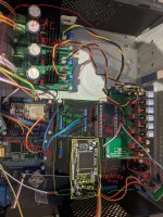
Tried my best, will add more if needed and sorry for getto style diy.
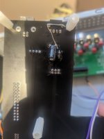
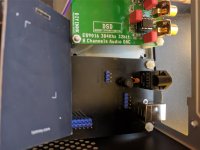
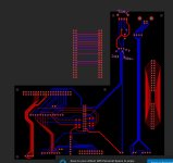
Board that is under dsp made myself.. 2 layer board, no ground or power plane just traces. I use the as adapter for non standard 2.0mm raster pins on dsp board.
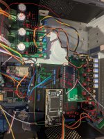
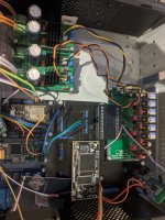
Right now csr8675 BT module is connected via goldpin close to dsp core board.
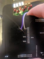
I did cut the traces to RX176 for testing. those are signal(violet) and ground(white)
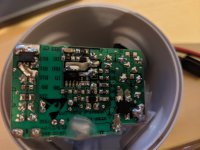
The PSU:
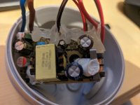
For now Im using cheap usb chargers, tested 2 of them with same result
DSP is powered through USB socket
1. Cant identify VR, think was around 1A
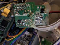
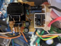
2. Think was 2A. VR: cre6255 2109WE http://www.cresemi.com/uploads/soft/200920/2-200920160949.pdf
Schematics pdf file for DSP in attachments
I have only core board so DSP_ADSP2148X, DSP_BUS is mainboard which i dont have
Looks like it use AMS117-3.3?
DAI_P17 is spdif input
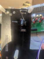
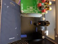
RX176 bottom and top view
but seriously:
You mean how long I need to have it powered off till noise disappear? Probably like 30-60min. Last time after 5min noise was the same.Which is time delay while the noise not ended?
Pictures usually say more than words. Revolutionary idea, I know. Imagine calling a workshop that you have “a car” with “some problem” making “some kind of noise” and “a lamp” glowing. Then ask yourself what the person at the other side of the line can do with that information. Exactly, you forgot to mention the cars color 😉
Tried my best, will add more if needed and sorry for getto style diy.
Board that is under dsp made myself.. 2 layer board, no ground or power plane just traces. I use the as adapter for non standard 2.0mm raster pins on dsp board.


Right now csr8675 BT module is connected via goldpin close to dsp core board.
I did cut the traces to RX176 for testing. those are signal(violet) and ground(white)

The PSU:
For now Im using cheap usb chargers, tested 2 of them with same result
DSP is powered through USB socket
1. Cant identify VR, think was around 1A


2. Think was 2A. VR: cre6255 2109WE http://www.cresemi.com/uploads/soft/200920/2-200920160949.pdf


Schematics pdf file for DSP in attachments
I have only core board so DSP_ADSP2148X, DSP_BUS is mainboard which i dont have
Looks like it use AMS117-3.3?
DAI_P17 is spdif input
RX176 bottom and top view


Attachments
Last edited:
Kicking in an open door: my suggestion is to use 78xx based regulators (or other linear regs if the current demands that) just for testing instead of the USB chargers. Please shorten cabling and route all cables neatly and as far away from circuits as possible. Looks better too. Then report back.
Keywords: "cheap" and "USB charger".
Strong advice to build safe. Those cheap USB chargers (opened) and not mechanically mounted are not safe. Build well or don't build at all.
Keywords: "cheap" and "USB charger".
Strong advice to build safe. Those cheap USB chargers (opened) and not mechanically mounted are not safe. Build well or don't build at all.
Last edited:
Project is in prototype phase, planned new PCB for adapter board, isolators added for i2s & i2c for DAC and of course proper PSU. Was looking for one on aliexpress before, but decided its better to buy good quality, non counterfeit parts and use someone's project... If you have any suggestions which project to use - simple with PCB layout please let me know.
I have spdif signal on bottom side of the board so will problem to make it really short, think I can do something like 4-5cm, will try that.
Is spdif signal really that much fragile than i2s?
No worries, when used I have then in thick plastic enclosures, not a fan of touching live wires🙂Strong advice to build safe. Those cheap USB chargers (opened) and not mechanically mounted are not safe. Build well or don't build at all.
I have spdif signal on bottom side of the board so will problem to make it really short, think I can do something like 4-5cm, will try that.
Is spdif signal really that much fragile than i2s?
Are you sure the problem is related to SPDIF, do you have other input sources that work okay? If only SPDIF how many clock domains do you have in that case? Is is possible clocks are drifting?
It might help if you could provide a block diagram of what you have there. What boards are being used, what signals are going between which boards, etc.
It might help if you could provide a block diagram of what you have there. What boards are being used, what signals are going between which boards, etc.
Its all on photos torx176 to dsp or csr8675 bluetooth to dsp, signal goes from TV or PC over toslink, or from mobile or TV over BT if thats what you mean.You'll better to use IEEE802.3 5E cat. wires from TORX to receiver, what SPDIF receiver are you using?..
And what's the signal's option are you using? I mean 24 bits 96 kHz or like that.
I will try to short the cables as much as I can first, maybe twist signal and gnd together?
I am guessing its 48khz from bluetooth, from TV not sure.
I will connect to PC and check also if it behave differently on different audio format.
I was suspecting some problem with ground, or that I made antenna from traces on my board by accident.. bad solder joint somewhere?Are you sure the problem is related to SPDIF, do you have other input sources that work okay? If only SPDIF how many clock domains do you have in that case? Is is possible clocks are drifting?
It might help if you could provide a block diagram of what you have there. What boards are being used, what signals are going between which boards, etc.
Will get better psu and shorten cables as @jean-paul suggested.
With i2s source - xmos or rapberry pi, everything works fine. csr8675 bluetooth also worked 'fine' on i2s.
so
rpi ---i2s-->dsp --i2s-->dac
xmos ---i2s-->dsp --i2s-->dac
csr8675 ---i2s-->dsp --i2s-->dac
is ok
csr8675 ---spdif-->dsp --i2s-->dac
torx176 ---spdif-->dsp --i2s-->dac
is not ok
to minimize fault factor, i connected as described, 1 source at a time
also I mentioned earlier i did check in sigmastudio, there is VU and I see noise on spdif input
DSP accept 96khz signal only over i2s and work @96khz internally, spif input got asrc, on board there are 3 oscillators 12.288Hz, 8MHz 24.576MHz think one of them might be faulty? Can I check without oscillator? Or you meant something else?If only SPDIF how many clock domains do you have in that case? Is is possible clocks are drifting?
So, are you saying the DSP board has a SPDIF input connector on it? From that connector the SPDIF gets signal conditioned then routed to an SPDIF input pin on the DSP chip where an internal ASRC resamples the SPDIF to 24/96?
Yes, check one of previous posts, I added schematics there. DAI_P17 is spdif input pin on core board from aliexpress. To that pin I connect either BT module or torx176So, are you saying the DSP board has a SPDIF input connector on it? From that connector the SPDIF gets signal conditioned then routed to an SPDIF input pin on the DSP chip where an internal ASRC resamples the SPDIF to 24/96?
Okay. Where is the torx176, how is it powered, how far away is it, is its output capacitor coupled, what kind of signal wiring are you using...50-ohm, does it have a termination resistor on the line between the torx176 and the SPDIF input on the DSP chip, etc.?
EDIT: Also, is the torx176 configured as shown below?

EDIT: Also, is the torx176 configured as shown below?
Last edited:
Okay. Where is the torx176, how is it powered, how far away is it, is its output capacitor coupled, what kind of signal wiring are you using...50-ohm, does it have a termination resistor on the line between the torx176 and the SPDIF input on the DSP chip, etc.?
EDIT: Also, is the torx176 configured as shown below?
I think so
Track length is about 13cm
I did try both 33 and 75ohm resistors on torx side
Output coupled? signal wiring 50ohm?.. dont think so, how to do it?
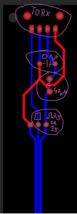
You could do it like:

Normally ground would go to a ground plane, maybe layer 2 of a 4 layer board. With the 33R resistor in series with the optical receiver output that makes it capable of driving a not too long 50-ohm transmission line. If you can't do that on your PCB and interconnect wiring, maybe better to just use a thin piece of 50-ohm coax from the right side of the 33-ohm resistor (as shown above) to the DSP board. Ground the coax at both ends or you could cap couple if LF ground loop problems (if you want or need to do that then there needs to be one or some resistors at the input of the DSP chip so the input has a path back to ground, unless it already has that internally). Also good to remember, you are dealing with RF with fast clock edges. The harmonic frequencies associated with those edges may extend up into the hundreds of MHz. The signals, bypass, ground plane use, etc., should be treated with some care and respect. Power should probably be the same power as for the DSP board.
Normally ground would go to a ground plane, maybe layer 2 of a 4 layer board. With the 33R resistor in series with the optical receiver output that makes it capable of driving a not too long 50-ohm transmission line. If you can't do that on your PCB and interconnect wiring, maybe better to just use a thin piece of 50-ohm coax from the right side of the 33-ohm resistor (as shown above) to the DSP board. Ground the coax at both ends or you could cap couple if LF ground loop problems (if you want or need to do that then there needs to be one or some resistors at the input of the DSP chip so the input has a path back to ground, unless it already has that internally). Also good to remember, you are dealing with RF with fast clock edges. The harmonic frequencies associated with those edges may extend up into the hundreds of MHz. The signals, bypass, ground plane use, etc., should be treated with some care and respect. Power should probably be the same power as for the DSP board.
Last edited:
The electrolytic probably isn't that critical, but the bypass cap should be as close as possible to the power and ground pins on the optical receiver. What about the inductor?
Also, do you have a scope? Freeze spray? If you are getting noise from the SPDIF input then the signal probably wouldn't look right on a scope. Could also be that the jitter is too much for the ASRC to track. Where did the torx176 come from, and is it new or used?
Also, do you have a scope? Freeze spray? If you are getting noise from the SPDIF input then the signal probably wouldn't look right on a scope. Could also be that the jitter is too much for the ASRC to track. Where did the torx176 come from, and is it new or used?
Electrolytic was added recently for testing. Now I see distance from legs is bigger than it should, ok if I remove 0.1uF cap and solder it directly to legs of torx176?The electrolytic probably isn't that critical, but the bypass cap should be as close as possible to the power and ground pins on the optical receiver. What about the inductor?
Also, do you have a scope? If you are getting noise from the SPDIF input then the signal probably wouldn't look right on a scope. Could also be that the jitter is too much for the ASRC to track. Where did the torx176 come from, and is it new or used?
I dont have scope unfortuenetely, only multimeter. If I had scope it would be first thing to connect it and see whats happening and post screens/video here🙂
Cant vouch for source of torx173, but if it was toslink fault then I guess csr8675 bluetooth would work at least..
Those are coils I used:
https://www.aliexpress.com/item/330....order_list.order_list_main.60.21ef1802WO3dkg
ceramic is just cheap one from ali for testingIt's for example. 🙂 What's type of ceramic is set on the torx176?
Your PCBs or kits from ali?.. 🙄
https://www.aliexpress.com/item/100...der_detail.order_detail_item.9.5818f19cxF5Bf5
But I did measure cap with multimeter and it show right value
Small dsp board is from aliexpress.
black board made myself, so probably there is the fault?
True. Sure would help to have a scope just to check. Does the DSP chip have any control and or status registers to configure the SPDIF inputs and or ASRC? Could be something is misconfigured, such as if something like ASRC loop bandwidth setting was too tight. Otherwise could be a bad DSP chip. How are the power supplies and bypassing looking for the DSP chip? How is the clocking working? If you think heat is the culprit and and you don't have any freeze spray it may be possible to let it cool then heat up one thing at time faster than usual. See if you can make the problem happen sooner. Maybe some clue could be found that way?...if it was toslink fault then I guess csr8675 bluetooth would work at least..
There are no settings for spdif or asrc, its all in firmware others who have this board use same firmware as I have and spdif working, I assume its fine.
I dont feel any heat from dsp even if its working longer, but I can check that later.
Power supply should be changed.
So things to check for me for now:
1. new PSU
2. check if there change in behaviour when i change spdif format 48khz, 96khz etc
3. Solder cap to legs of torx
Anything else?
Im looking for decent and simple PSU with 78xx voltage regulator or other?
If you know any good project with simple PCB I could make at home please let me know.
5V and 2A would be perfect
- Home
- Source & Line
- Digital Source
- S/PDIF input problem
