Hello everyone,
I recently looked into boxes of tubes that I collected over the years and found out to have 20 ECL82/6F3P/PCL82. Some of these look slightly used, but others are crystal clear (even NOS in boxes). I would like to build a guitar amp for a clean jazzy tone, getting around 6-7W in PP would be more than fine for me.
I would like to make a hybrid construction rather than making another clone of something common (I have already built amps in the past so I know something). I like the idea of having only 2 bottles for the whole amp. Since hybrid amps are new for me, I would like to deepen this topic and learn something new, so I decided to ask here for some pro tips 🙂
When I started thinking about the design, I came up with an idea of using hybrid cascode in the inverter, with JFETs as lower devices. Quick simulation of such a design has shown that plenty of gain is achieved (obvious) and it might work. Also found this thread:
https://www.diyaudio.com/community/threads/calling-yves.102553/
where gingertube mentioned such a configuration for ECL82.
I have a PT dedicated for ECL/PCL tubes, which has a 13V tap for PCL heaters. I can use 13V to obtain -15V for the purpose of CCS and preamp section. However, my concern is feedback, I would like to tame the gain but have no clue how to make it properly. Initial idea was to apply GNF from the OT to the "+" input of a differential opamp driving the inverter, but I am not sure this is a good way of doing it (long feedback path?). Besides, due to 0:-15V supply I would have to create artificial ground for opamps so using transistor stages might be a better idea. I was fooling around plate-to-plate feedback from output tubes to the inverter (shortest path), but could not get meaningful results in spice. I also consider using UL...
Regarding preamp, I want to have simple low/high correction and rather flat characteristics. Since cascode provides a lot of gain, the preamp section would not have to deliver a lot of amplification (at least that's how I see it). Maybe experienced users of this board could suggest something to me? Since this will be a guitar amp, the THD is not the most important matter.
Here's the schematics I've been working on.
You don't need the op-amp take the NFB to the JFET on the right. The guitar input goes to the jfet on the left. Use 1M input or you will load the pickups.
I will be using ECL82 only.
Regarding feedback - I could not achieve proper results using right transistor input of cascode. I reworkd preamp to use transistors rather than opamps, I also changed fets to bjts in cascode. Problem I see is that gain of cascode seems to big - I only need 200mV p2p to drive output tubes to full power.

Regarding feedback - I could not achieve proper results using right transistor input of cascode. I reworkd preamp to use transistors rather than opamps, I also changed fets to bjts in cascode. Problem I see is that gain of cascode seems to big - I only need 200mV p2p to drive output tubes to full power.

Well, I have flipped around OT wirings in my simulation, applied NF to cascode's right transistor input and now works fine...
In my experience you don't need a cascode driving the ECL82 pentodes. You will need about 40V grid-to grid for 10-11W out at about 3-4% THD with 5-7K transformer in pentode mode; 6-7 W if Ultralinear with even less distortion. With Ultralinear you won't need any feedback as 1-2% THD at max Pout is nothing. This is not HiFi.
In my guitar amps I do not use feedback in pentode mode either as there is plenty of choice for speaker drivers anyway but that's personal taste. I find that using fbk one ends up with the typical Fender style sound which is great for blues but not my favourite for jazz.
For example, for jazz sound I like a lot some Alnico drivers like the Celestion G10 Gold or the Eminence Legend 1028K. If output power is not a strict requirement you can also play with primary load of output transformer.
One great jazzy sound I got was with the Eminence above +16K plate-to-plate for PCL86 running in pentode mode at 300V plate voltage + cathode bias (approx. 30mA per tube) for 10W output. I used the cheap Polamp PCL86s. The gain of LTP with CCS tail will be enough. Put a master volume control at the input and then the front-end can be everything you desire provided it has a proper line level output. Also, for the LTP one triode gets the direct dignal and the other can be used to mix it with the reverb signal.
You can do the same with the '82s.
Last edited:
Thx for tips.
I actually want to use cascode mainly due to my curiosity - it might be an overengineering but still worth testing 🙂
Currently I got PT for EL84 (8k plate to plate) which I am considering using, the datasheet for ECL82 mentions 10k but small imbalance should be fine too. If I find UL OT then I’ll consider removing feedback. My PT gives 210V@100mA, so I expect ~250V on anodes of pentodes.
I have tuned the circuit to deliver 40V grid to grid for 100mV input signal (~9.5db feedback signal). I know that ECL86s are better, but ECL82s are cheap, and as mentioned - I’ve got dozens of these (Polam/Telam, these were really good tubes). Heck, I think that I just build the amp and fine tune it.
I quite liked your jfet solution. Low noise and high input impedance. You are going to have troubles with 1M on the NPN as you can see with the base voltage and that's if they are matched. Gain too high - increase source/emitter resistors.
I actually returned to jfets idea after figuring out the feedback issue. I think that 100k in gates should be fine. With jfets more caution regarding voltages must be kept though.

I don't agree that 86's are better. The 82's are just as good. In my opinion you should go ahead and don't change the tube until you try it.😉Thx for tips.
I actually want to use cascode mainly due to my curiosity - it might be an overengineering but still worth testing 🙂
Currently I got PT for EL84 (8k plate to plate) which I am considering using, the datasheet for ECL82 mentions 10k but small imbalance should be fine too. If I find UL OT then I’ll consider removing feedback. My PT gives 210V@100mA, so I expect ~250V on anodes of pentodes.
I have tuned the circuit to deliver 40V grid to grid for 100mV input signal (~9.5db feedback signal). I know that ECL86s are better, but ECL82s are cheap, and as mentioned - I’ve got dozens of these (Polam/Telam, these were really good tubes). Heck, I think that I just build the amp and fine tune it.
In pentode mode with 230V supply and cathode bias you can get 10W with 7K plate-to-plate. With 250V, 8K will be fine.
For the preamp part, make sure the very first stage (and of course all the others) can accept up to 1.5V peak from the pick-ups without distorting if you are looking for clean sound all the time. Although the average signal level is around 20-100 mV and peaks up to 200-300mV most of the time, many guitars can easily output 1-1.5V peak when the cord is struck with some energy. The initial peak is a very short transient but it has fundamental role in defining the sound.
You don't need C9, R28. In fact this will make the LF stability worse. If you want to drop the gain increase R12, R26. You may need to make this a trimmer to balance the FETs. I would make R36 470K as guitar pickups prefer higher loads. The JET will giver lower noise than just the valve only so you can use the guitar volume to wind down the gain.
You can also return the CCS to 0V, use R30 to bias Q1 and Q2 instead of R9. That way you won't need a negative rail. Just gets simpler. You may wish to add a couple of grid stoppers.
If you intend to unplug the speaker add reverse protection diodes from each output plate to ground or have 50R to ground in parallel with speaker.
Last edited:
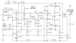
Thanks for comments. Full schematic below as how I think I will proceed with an amp:

My intention is to use -15 (from 13V AC tap) to power both preamp and CCS as it seems the logical way of doing it. On the other hand, removing negative rail and connecting CCS to would reduce gain (which is fine as there is plenty of), so I could use +15V to supply the preamp (would have to rework it). Will think about it.
Also I was thinking that if this amp works fine, I may try to build a similar design but with different tubes (got a bunch of ECC85 and ECC88 laying around).
All in all, I will start designing PCB for the amp soon.
ps. R59 is only for simulation purpose. R24 just to fine tune gain in a real amp.
Attachments
I don't think you need J1 and J2. There should be enough gain in J5/J4 stages to compensate for the lower LTP gain. Also, as @baudouin0 said, you do no need R28 and C9.
I know that J1 and J2 are not needed, but I want to do a little bit of overengineering for the sake of fun. Indeed I can remove R28 and C9. I will add some gate stoppers at the inputs of J1/J2.
Oh, and I've got an idea to add tremolo signal to the triode's grids in the future...
Oh, and I've got an idea to add tremolo signal to the triode's grids in the future...
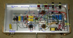
Another amp with a Cascoded Differential amp, this time on the front end. As I did during 25 yrs ago, I had specific items I wanted to try as well as the front end.
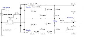
The PP 6V6s are driven & loaded to run in Class AB2. The B+ of the PS is a small PT so that test of limited PS is possible. The 6V6 control grids are direct coupled to 6BQ7 triodes as drivers so that positive grid current is possible. An odd kind of cross coupled internal NFB is used. The upper triodes of the cascade are a 4BQ7 so that the otherwise unused 5V winding on the PS is used for the heater, no H-K insulation problems.
Using its own limited PS the amp manages 19 watts. Boosting the amps B+ back to normal with a lab supply, output at clipping is about 26 watts. This kind of performance is about what some of the guitar amps are setup for.
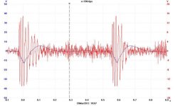
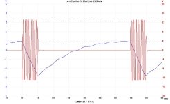
In the pulse test here a 1000 Hz signal is on for 12 mS. If we do the numbers the 9V drop on the 100 microF PS cap looks like 75 mA for that period.
And its not pretty. In spite of all this, it ‘sounds’ OK. Whatever that is! 👍 😀
The PP 6V6s are driven & loaded to run in Class AB2. The B+ of the PS is a small PT so that test of limited PS is possible. The 6V6 control grids are direct coupled to 6BQ7 triodes as drivers so that positive grid current is possible. An odd kind of cross coupled internal NFB is used. The upper triodes of the cascade are a 4BQ7 so that the otherwise unused 5V winding on the PS is used for the heater, no H-K insulation problems.
Using its own limited PS the amp manages 19 watts. Boosting the amps B+ back to normal with a lab supply, output at clipping is about 26 watts. This kind of performance is about what some of the guitar amps are setup for.
In the pulse test here a 1000 Hz signal is on for 12 mS. If we do the numbers the 9V drop on the 100 microF PS cap looks like 75 mA for that period.
And its not pretty. In spite of all this, it ‘sounds’ OK. Whatever that is! 👍 😀
Attachments
-
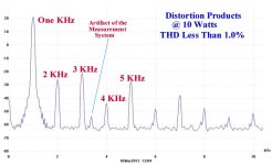 Distortion Products at 10 Watts B.jpg37.7 KB · Views: 112
 -
 IMG_1383 Cascode Amp Bottom A 14W E Flash Labelled.jpg437.1 KB · Views: 104
 -
 2013_03_21_001 Peter Gabriel Salsbury Hill 8W.jpg28.6 KB · Views: 99
 -
 2013_03_23_002 10 Watt Pulses.jpg56.9 KB · Views: 110
 -
 IMG_1383 Cascode Amp Bottom A 14W E Flash Labelled.jpg437.1 KB · Views: 118
 -
 026 Cascode Amp A.JPG710.7 KB · Views: 148
 -
 Cascode Amp H.JPG54.8 KB · Views: 155
 -
 Cascode Amp PS B.JPG47.4 KB · Views: 135
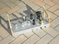
I like the layout of your amp. Power tubes vertically to pi/preamp is not something popular these days, however, I think it kind of more natural and looks cool.
For the experimental amps I've built, they are all intended to be inverted most of the time.
That way measurements & adjustments are easily made. None of them will ever sit on a bookshelf.
They are from the ground up my way of trying different & at times odd circuits.
Williamsons, Dynas, Mullards & on & on have been built many times by others.
Nothing new to look at or solve there. Not very interesting at all. 😀
Full schematic below as how I think I will proceed with an amp:
I wonder what the TND level is at the cathodes of the input triode?
p100: Also I was thinking that if this amp works fine, I may try to build a similar design but with different tubes (got a bunch of ECC85 and ECC88 laying around).
.....
. Guitar players' don't accept every sound. So you think ث ecc85... and ecc88 ... are interesting for guitar amp ? Guitar amplifiers are never like hi-fi and don't have a linear response.....ccs !!!!!!for guitar amp .....
.....
. Guitar players' don't accept every sound. So you think ث ecc85... and ecc88 ... are interesting for guitar amp ? Guitar amplifiers are never like hi-fi and don't have a linear response.....ccs !!!!!!for guitar amp .....
- Home
- Amplifiers
- Tubes / Valves
- PP ECL82 amp with cascode inverter