Historical Background
Spoiler alert: strong heresy inside – Collectors please bail out NOW!
I know the Leak brand by reputation, and it has a very strong following, even today. I had the opportunity to buy this Leak ST60 at the local flea market in the 80’s. I don’t remember what I paid, but it wasn’t exorbitant like it is nowadays.
I cleaned it up, re-tubed, replaced most capacitors, had a listen, and was disappointed: the sound was anemic, devoid of finer details, your typical “warm and fuzzy” sound of vintage gear. Maybe a tiny bit better than the old Quad II, but barely so.
It went on a long-term loan to a friend’s who didn’t like it either; it came back dead after a few months and spent many a year in a closet.


As-Is
The topology is loosely based on the Mullard circuit. Possibly to meet the high gain requirement of yesteryear, they used a 12AX7/ECC83 for the phase inverter, running at only about 0.8mA per leg. A most unfortunate design choice, shared only by Jadis AFAIK (and Mullard, but Mullard didn’t sell amps for a living).
Also questionable is the UL tap at 25%: this lets them extract a bit more power, at the expense of a more pentode-like behavior.
On top of questionable engineering decisions, I also have the feeling it was a company run by bean counters: the output transformer 5 layers S/P/S/P/S, like a Dynaco, OK for mid-Fi.

But IMHO, 7 layers is the more “natural” configuration for ultra-linear, as illustrated here:

Some of the upper-tier winders use 9 layers, and P. J. Walker (RIP), a direct competitor, went as far as 13 layers in the Quad II (I just love PJ's go for broke approach)!
Back to the ST60: another thing I don’t like is the 0.3H choke: this is the smallest one I’ve seen in any amp, decent or otherwise! Just enough to get away with it, right, guys? Me, I’m not even sure it’s enough to protect the GZ34 before it from the brutality of the 360uF reservoir caps I use.
So, the philosophical question: what justifies the cult-like following of this brand?
Measurements, then
At the time of purchase, the THD, the Holy Grail according to Leak’s selling pitch, is kind of OK, at about 0.2% at 1kc/s. The biggest surprise is the open loop bandwidth: a whopping 3kc/s (you read right: three thousand cycles per second), worthy of an IC opamp!!!
The gear I used at that time was the very temperamental Radford DMS 3 (<0.002% THD).

Also, the power vs load is narrower than that of an ARC D70. This is surprising because the D70 is almost a true tetrode design with only a small amount of cathode feedback, while the ST60 is ultra-linear, but only at 25%.

Some 40 years after the fact, I decided to take it out of the closet and see if I could make it better, without doing anything drastic like drilling holes or otherwise butchering the chassis.
The objectives
My priorities are:
The mods
First thing first: the ECC83 in the phase inverter must go: what I have in mind is the superb E80CC. Because they don’t come easy, my plan B is the 12BH7: they are electrically similar enough to be considered drop-in replacements. A bit over 3mA per leg should do nicely, and a tail of 18K lets me direct couple the phase inverter to the input tube, saving a low frequency pole. A small trim pot is added to a plate resistor to balance the amp.
The input ECC83 will have to go too: nothing wrong with it, just too much gain. The ECC81/12AT7 I picked is a questionable choice, I know: it’s the least linear of the popular ECC81/2/3 trio. We’ll see.
The purpose of these mods is to fulfill prio #2 above, which fulfills prio #1.
High bandwidth, low feedback, “This Is The Way”.
The output stage is largely unchanged, even though I’m not comfy with self-biasing. But lots of Brits love it, so why not? The only minor tweaks are:
Plea of guilt: I stole many ideas from the excellent article Kara Chaffee published in the March 2001 issue of Audio Xpress.
The power supply
The power supply is beefed up with a couple of Nichicon 180uF 600V, bypassed with 0.1uF MKP; don’t cheap out on the voltage ratings. Additional filtering for the low-level stages with 2x50uF by JJ, bypassed as well; these are slightly less good than the Nichicon, with D = 0.2 vs 0.1 for the Japanese, after reforming. I also added snubbers and a ground breaker.

The sim

This looks good on screen: THD down an order of magnitude, open-loop bandwidth up >15x.
Life is good… just DON’T BUILD THIS!
The tube line-up for the measurements
NB1: Ia & Gm are from my Metrix U61B tube tester – They are not operating conditions in the amp. And yes, V3L is quite a bit off, even though I paid the price for a “matched” quad.
NB2: the E81CC is probably a relabeled Tesla. They’re alright.
The reality
Life is hard. The output transformer is hard. Modeling the output trafo is just as hard. Measuring this whole affair is not any easier.
After implementing all the mods and tweaking the balance pot of the PI for minimum THD, I played it safe and did an open-loop test, so far so good:

The open loop performance is not too shabby. I even suspect I could live with it as is, maybe with an ECC82 at the input to further reduce the gain, or even omit it all together, à la Fender.
But as soon as I close the FB loop, it oscillates, of course. This is expected, but the OPT model I’m using rules out any solution by simulation. Also, the limitations of my digital instrumentation make me blind: anyone sees anything beyond the right-hand side of the chart above? Too bad, it’s the limit of the sampling frequency.
The archeology
A little digging brings out some long-forgotten treasures: a vintage HP 3400A RMS voltmeter, a B&K 3010 function generator, pen, paper, and Excel. I know, a gadget like the Analog Discovery 2 would make my life less miserable, but I don’t have it. Or maybe E1DA’s Cosmos ADC: it should do 384KHz; this one is on my to-buy list. Anyway, here’s what gives, with my vintage all-analog lab:
Open loop, no compensation:

Voilà: the dip at 70KHz and the peak at 90KHz are compliment of the OPT and ignored by the digital gear. Who says life in audio stops at 20KHz? Gimme 1MHz anytime!
Don’t pay attention to the anomaly at 10Hz, probably a human error: remember, it’s pen and paper time. And the early roll-off of the bass is caused by the small cathode bypass.
Now I can trial-and-error (not a verb) my merry way. Simple enough:
The closed-loop gain is 17.5 or 25dB, for 18dB of feedback.
The overall stability margin is better than 6dB.
Closed loop, ultra-linear:

Triode:

Square wave UL mode 8R load

Just a tiny bit of oscillation caused by the self-resonance. Patrick Turner (RIP) suggested the use of a small ferrite (evil!) inductor. Me, I see no reason why I should let in yet another reactive meanie, even an air-cored one, so I just ignore it.
Square wave UL mode 8R+1uF load

Square wave Triode mode 8R load

Square wave Triode mode 8R+1uF load

Final schematic

I’m attaching all the LTspice stuff, including the stolen ones. If I forgot to give credits to any rightful owners, please take this as my group apology.
Spice: postmortem
The first output transformer model I used is from McLean; it doesn’t model the parasitic capacitances, and so the self-resonance doesn’t show up. Of course, you can add series/parallel caps externally, but I don’t feel comfy with the results: in order to approximate the experimental findings, I have to add series caps (prim to sec) of the order of 10nF instead of the measured 2-3nF, which doesn’t add up.
The second model is from Ite, it supports parasitic capacitances, but it also has similar discrepancies as the first one.
Any output transformer AND LTspice guru out there?
Btw, in LTspice, the .ac command almost always converge; .trans will converge if the circuit is not oscillating too badly. IOW, during a .tran sim, if nothing useful happens after a few seconds, halt and add more compensation.
Totally OT side note: the new version of the forum software no longer limits the length of a post. However, you can't attach more than 20 items at a time.
TBC...
Spoiler alert: strong heresy inside – Collectors please bail out NOW!
I know the Leak brand by reputation, and it has a very strong following, even today. I had the opportunity to buy this Leak ST60 at the local flea market in the 80’s. I don’t remember what I paid, but it wasn’t exorbitant like it is nowadays.
I cleaned it up, re-tubed, replaced most capacitors, had a listen, and was disappointed: the sound was anemic, devoid of finer details, your typical “warm and fuzzy” sound of vintage gear. Maybe a tiny bit better than the old Quad II, but barely so.
It went on a long-term loan to a friend’s who didn’t like it either; it came back dead after a few months and spent many a year in a closet.
As-Is
The topology is loosely based on the Mullard circuit. Possibly to meet the high gain requirement of yesteryear, they used a 12AX7/ECC83 for the phase inverter, running at only about 0.8mA per leg. A most unfortunate design choice, shared only by Jadis AFAIK (and Mullard, but Mullard didn’t sell amps for a living).
Also questionable is the UL tap at 25%: this lets them extract a bit more power, at the expense of a more pentode-like behavior.
On top of questionable engineering decisions, I also have the feeling it was a company run by bean counters: the output transformer 5 layers S/P/S/P/S, like a Dynaco, OK for mid-Fi.
But IMHO, 7 layers is the more “natural” configuration for ultra-linear, as illustrated here:
Some of the upper-tier winders use 9 layers, and P. J. Walker (RIP), a direct competitor, went as far as 13 layers in the Quad II (I just love PJ's go for broke approach)!
As a side note, here’s my plea to all commercial winders: please publish at least:
- The frequency response graph to min. 200KHz
- All inductances
- All capacitances
- If possible, distortion vs frequency graph
If you don’t, I’ll assume you don’t know what you’re talking about, and I’ll call the next guy in line. FYI, Partridge did nearly this, almost a century ago!
Back to the ST60: another thing I don’t like is the 0.3H choke: this is the smallest one I’ve seen in any amp, decent or otherwise! Just enough to get away with it, right, guys? Me, I’m not even sure it’s enough to protect the GZ34 before it from the brutality of the 360uF reservoir caps I use.
So, the philosophical question: what justifies the cult-like following of this brand?
Measurements, then
At the time of purchase, the THD, the Holy Grail according to Leak’s selling pitch, is kind of OK, at about 0.2% at 1kc/s. The biggest surprise is the open loop bandwidth: a whopping 3kc/s (you read right: three thousand cycles per second), worthy of an IC opamp!!!
The gear I used at that time was the very temperamental Radford DMS 3 (<0.002% THD).
Also, the power vs load is narrower than that of an ARC D70. This is surprising because the D70 is almost a true tetrode design with only a small amount of cathode feedback, while the ST60 is ultra-linear, but only at 25%.
Some 40 years after the fact, I decided to take it out of the closet and see if I could make it better, without doing anything drastic like drilling holes or otherwise butchering the chassis.
The objectives
My priorities are:
- De-opamp (not a verb) by moving the dominant pole to 10KHz or more.
- De-starve (not a verb) the low-level stages.
- Reduce the overall gain and the loop gain.
- Nice to have: add a triode pentode switch.
The mods
First thing first: the ECC83 in the phase inverter must go: what I have in mind is the superb E80CC. Because they don’t come easy, my plan B is the 12BH7: they are electrically similar enough to be considered drop-in replacements. A bit over 3mA per leg should do nicely, and a tail of 18K lets me direct couple the phase inverter to the input tube, saving a low frequency pole. A small trim pot is added to a plate resistor to balance the amp.
The input ECC83 will have to go too: nothing wrong with it, just too much gain. The ECC81/12AT7 I picked is a questionable choice, I know: it’s the least linear of the popular ECC81/2/3 trio. We’ll see.
The purpose of these mods is to fulfill prio #2 above, which fulfills prio #1.
High bandwidth, low feedback, “This Is The Way”.
The output stage is largely unchanged, even though I’m not comfy with self-biasing. But lots of Brits love it, so why not? The only minor tweaks are:
- Grid leaks are changed from the original 680K down to 470K as per the datasheet.
- 100R screen-grid stopper resistors are added.
- A triode/pentode switch is added.
Plea of guilt: I stole many ideas from the excellent article Kara Chaffee published in the March 2001 issue of Audio Xpress.
The power supply
The power supply is beefed up with a couple of Nichicon 180uF 600V, bypassed with 0.1uF MKP; don’t cheap out on the voltage ratings. Additional filtering for the low-level stages with 2x50uF by JJ, bypassed as well; these are slightly less good than the Nichicon, with D = 0.2 vs 0.1 for the Japanese, after reforming. I also added snubbers and a ground breaker.
The sim
This looks good on screen: THD down an order of magnitude, open-loop bandwidth up >15x.
Life is good… just DON’T BUILD THIS!
The tube line-up for the measurements
| Pos. | Id | Status | Brand | Type | Ia (mA) | Gm (mA/V) |
| V3R | 1 | NOS | =C= / SED | EL34 | 82 | 10 |
| V4R | 3 | NOS | =C= / SED | EL34 | 83 | 10 |
| V3L | 2 | NOS | =C= / SED | EL34 | 70 | 9 |
| V4L | 4 | NOS | =C= / SED | EL34 | 81 | 10 |
| V2R | 11 | Used | RCA | 12BH7A | 9.3/9.6 | 2.9/3.0 |
| V2L | 10 | Used | RCA | 12BH7A | 9.0/10.2 | 2.2/2.6 |
| V1 | 19 | Used | Siemens | E81CC | 7.0/8.2 | |
| V5 | NOS | Sovtek | GZ34 |
NB1: Ia & Gm are from my Metrix U61B tube tester – They are not operating conditions in the amp. And yes, V3L is quite a bit off, even though I paid the price for a “matched” quad.
NB2: the E81CC is probably a relabeled Tesla. They’re alright.
The reality
Life is hard. The output transformer is hard. Modeling the output trafo is just as hard. Measuring this whole affair is not any easier.
After implementing all the mods and tweaking the balance pot of the PI for minimum THD, I played it safe and did an open-loop test, so far so good:
The open loop performance is not too shabby. I even suspect I could live with it as is, maybe with an ECC82 at the input to further reduce the gain, or even omit it all together, à la Fender.
But as soon as I close the FB loop, it oscillates, of course. This is expected, but the OPT model I’m using rules out any solution by simulation. Also, the limitations of my digital instrumentation make me blind: anyone sees anything beyond the right-hand side of the chart above? Too bad, it’s the limit of the sampling frequency.
The archeology
A little digging brings out some long-forgotten treasures: a vintage HP 3400A RMS voltmeter, a B&K 3010 function generator, pen, paper, and Excel. I know, a gadget like the Analog Discovery 2 would make my life less miserable, but I don’t have it. Or maybe E1DA’s Cosmos ADC: it should do 384KHz; this one is on my to-buy list. Anyway, here’s what gives, with my vintage all-analog lab:
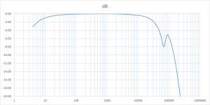
Open loop, no compensation:
Voilà: the dip at 70KHz and the peak at 90KHz are compliment of the OPT and ignored by the digital gear. Who says life in audio stops at 20KHz? Gimme 1MHz anytime!
Don’t pay attention to the anomaly at 10Hz, probably a human error: remember, it’s pen and paper time. And the early roll-off of the bass is caused by the small cathode bypass.
Now I can trial-and-error (not a verb) my merry way. Simple enough:
- Feedback resistor is 1.2K
- Drop the lag-zero resistor R21.
- Remove the lead cap C9 for the moment.
- Mess with the lag cap C16. The OK-ish range is between 200 and 680p. I picked 390p, 630V polystyrene because that’s what I have.
- Mess with the lead cap for the least bad compromise: it moves the peak up/down and left/right a bit; the OK-ish range is 1-2nF. I chose 1680p: 1nF // 680p, polystyrene too; the choice is also inventory bound. There’s no magic value that eliminate the resonance.
The closed-loop gain is 17.5 or 25dB, for 18dB of feedback.
The overall stability margin is better than 6dB.
Closed loop, ultra-linear:
Triode:
Square wave UL mode 8R load
Just a tiny bit of oscillation caused by the self-resonance. Patrick Turner (RIP) suggested the use of a small ferrite (evil!) inductor. Me, I see no reason why I should let in yet another reactive meanie, even an air-cored one, so I just ignore it.
Square wave UL mode 8R+1uF load
Square wave Triode mode 8R load
Square wave Triode mode 8R+1uF load
Final schematic
I’m attaching all the LTspice stuff, including the stolen ones. If I forgot to give credits to any rightful owners, please take this as my group apology.
Spice: postmortem
The first output transformer model I used is from McLean; it doesn’t model the parasitic capacitances, and so the self-resonance doesn’t show up. Of course, you can add series/parallel caps externally, but I don’t feel comfy with the results: in order to approximate the experimental findings, I have to add series caps (prim to sec) of the order of 10nF instead of the measured 2-3nF, which doesn’t add up.
The second model is from Ite, it supports parasitic capacitances, but it also has similar discrepancies as the first one.
Any output transformer AND LTspice guru out there?
Btw, in LTspice, the .ac command almost always converge; .trans will converge if the circuit is not oscillating too badly. IOW, during a .tran sim, if nothing useful happens after a few seconds, halt and add more compensation.
Totally OT side note: the new version of the forum software no longer limits the length of a post. However, you can't attach more than 20 items at a time.
TBC...
Attachments

The good
Smooth sailing from here on.
Some results at 15W 8R for comparison with my initial measurements on the factory item:


Triode

The IMD is also period-correct:


The ugly
Of course, compared to today’s Ultra-Fi (not an endorsement), there are shortcomings, the noise floor in particular: mains related noise spike at about -60dB, with the 3rd & 5th harmonics prominent:

Fear not: this thingy looks real ugly, especially with the SMPT IMD, but it’s harmless: I don’t hear any hum or noise with my (low efficiency) headphones. And it’s only 0.7mVrms at the output, according to the analog meter. Because it’s mostly low frequencies, there’s no need to fix the noise bandwidth. So the S/N ratio is about -87dB re. rated power. Plenty good enough, even for R&R!
If I were to really tackle this:
TBC.
The Result
From the outside, nothing has changed, except electrolytics.


From the inside, a small L shaped AL extrusion is used for the 1st reservoir capacitor, the snubbers, and the triode-pentode switch. It bolts on the fixing screws of the reservoir capacitors.

The listening
The amp is sitting on my bench, fed with a lowly Topping DX1 DAC (on sale for US$71 shipped!), and driving my Jecklin Float electrostatic headphones with a stock power supply. The first experience is not pleasant: lots of sibilants and flappy bass. I swap out the Russian rectifier for a NOS Mullard GZ34: immediately, it sounds louder and tighter. No surprise, the Sovtek is a known bad tube, good for sacrificial purposes only; it must have much higher internal resistance.
I still need to give the amp time to properly break in. Message to the non-believers: break-in is very real, even though I’ve already pre-reformed (not a verb) all the brand new electrolytics.
Over the following couple of days, the sound gets more pleasant: the hi’s smoothed out and the low’s tightened up. It’s still too early to give any definitive opinion, but I feel no urge to turn it off, and that’s a good start. For now, and in triode mode, I’d say the sound is a bit more refined but lacks the “in your face” sort of impact and 3D effect when compared to my heavily modified MC240, or other American muscle amps such as the ARC’s.
I briefly tried a quad of new JJ 6L6GC’s. They’re slightly low in terms of plate current, but they drop-in alright, as advertised. The sound is a bit bland and squashed, so back to the closet they go; again, this is a known fact. AFAIK, the Near Old Stock SED/Winged C EL34 from St. Pete are still the best deal in town.
To be continued, after I tried it with my Quad ESL57.
Smooth sailing from here on.
Some results at 15W 8R for comparison with my initial measurements on the factory item:
- The dominant pole is now 20KHz, a 6x improvement.
- The distortions start rising at about 6KHz, a 2x improvement.
- The THD at 1KHz remains about the same, despite the reduction in global feedback.
- The THD at 10KHz is now 0.17%, a 2x improvement.
Triode
The IMD is also period-correct:
The ugly
Of course, compared to today’s Ultra-Fi (not an endorsement), there are shortcomings, the noise floor in particular: mains related noise spike at about -60dB, with the 3rd & 5th harmonics prominent:
Fear not: this thingy looks real ugly, especially with the SMPT IMD, but it’s harmless: I don’t hear any hum or noise with my (low efficiency) headphones. And it’s only 0.7mVrms at the output, according to the analog meter. Because it’s mostly low frequencies, there’s no need to fix the noise bandwidth. So the S/N ratio is about -87dB re. rated power. Plenty good enough, even for R&R!
If I were to really tackle this:
- Adding a shield , Al or Fe, to the input tube yields no significant change.
- With 360uF of filtering, the HV should be quiet enough.
- The internal wiring is notoriously terrible. Maybe removing the heater supply from the harness could help?
- Maybe DC heater for the input tube?
- Maybe radiation from the transformers?
TBC.
The Result
From the outside, nothing has changed, except electrolytics.
From the inside, a small L shaped AL extrusion is used for the 1st reservoir capacitor, the snubbers, and the triode-pentode switch. It bolts on the fixing screws of the reservoir capacitors.
The listening
The amp is sitting on my bench, fed with a lowly Topping DX1 DAC (on sale for US$71 shipped!), and driving my Jecklin Float electrostatic headphones with a stock power supply. The first experience is not pleasant: lots of sibilants and flappy bass. I swap out the Russian rectifier for a NOS Mullard GZ34: immediately, it sounds louder and tighter. No surprise, the Sovtek is a known bad tube, good for sacrificial purposes only; it must have much higher internal resistance.
I still need to give the amp time to properly break in. Message to the non-believers: break-in is very real, even though I’ve already pre-reformed (not a verb) all the brand new electrolytics.
Over the following couple of days, the sound gets more pleasant: the hi’s smoothed out and the low’s tightened up. It’s still too early to give any definitive opinion, but I feel no urge to turn it off, and that’s a good start. For now, and in triode mode, I’d say the sound is a bit more refined but lacks the “in your face” sort of impact and 3D effect when compared to my heavily modified MC240, or other American muscle amps such as the ARC’s.
I briefly tried a quad of new JJ 6L6GC’s. They’re slightly low in terms of plate current, but they drop-in alright, as advertised. The sound is a bit bland and squashed, so back to the closet they go; again, this is a known fact. AFAIK, the Near Old Stock SED/Winged C EL34 from St. Pete are still the best deal in town.
To be continued, after I tried it with my Quad ESL57.
Very interesting reading! Thank you for sharing your journey and good luck with the next part on your ESL57s. I will have to re-read it it to gleen all the useful bits of information.
Interesting read, thanks! From your comments about the previous rectifier tube, is there even a place for a tube rectifier in the final incarnation?
That's a qualified yes, if you had the good stuff, e.g. Mullard/Philips GZ34. I'm fortunate enough to have 1 each black base and metal base; I'd never trade them for anything. That being said, I don't think the Sovtek I use for testing stands a chance against the better Schottky's. See Mark Johnson's excellent article in Linear Audio.
With solid state rectifiers, there're other factors that may come into play: possible excess HV, need for a slow turn on, and so on.
With solid state rectifiers, there're other factors that may come into play: possible excess HV, need for a slow turn on, and so on.
Errata:
- In the schematic, the feedback is taken from the 8 ohms tap of the OPT. It should be from the 16R tap as in the original circuit. For some reasons, the circuit oscillates, in simulation only, when using the 16R tap, even after I reduced the FB.
- Also in the schematic, Vpp should be Vp (peak voltage).
The 0.3H choke is a major mistake which they revised, I believe to 3H, as can be seen in some photos: the new choke is about 3x the height, which figures. I found a Hammond 3H which fits. As is, the PSU has a a peak at 72Hz, which isn't convenient.
You can remove the cathode bypass caps from V1 to reduce the OL gain: I find most Leaks are near to motorboating, and if you increase the NFB you can hit it. You can also reduce the enormous coupling caps, say to 0.047uF.
It isn't historically correct to say it's based on the Mullard circuit. Leak were using this one from about 1949, well before the Mullard articles were published.
EJP
"The 0.3H choke,,,"
Good to know someone at Leak dare defy the bean counters. 🙂
"... Leaks are near to motorboating..."
Poor design: the root cause is the close proximity of all the low frequency poles. This is easy to see with a simulator. Moving anyone of the poles up or down by, say, a decade will cure this, but it ain't free.
"... historically correct..."
Lost in the haze of time...
You're right, even though there're some fuzz factors. As far as I can tell:
Mullard:
I actually own a single TL/10 .1 that I restored to near factory specs with just some light mods to fit a pair of NOS Mullard EL33. But, honestly, it ain't much, and I'm not gonna do much. I'll off load it as soon as I find a way to add an RCA socket without drilling.

Good to know someone at Leak dare defy the bean counters. 🙂
"... Leaks are near to motorboating..."
Poor design: the root cause is the close proximity of all the low frequency poles. This is easy to see with a simulator. Moving anyone of the poles up or down by, say, a decade will cure this, but it ain't free.
"... historically correct..."
Lost in the haze of time...
You're right, even though there're some fuzz factors. As far as I can tell:
Mullard:
- 1954: 1st know publication of the Mullard 5-10
- 1955: publication of the "20-Watt High Quality Amplifier" in the Wireless World, May 1955
- 1959: publication of "Circuits For Audio Amplifiers", a compilation of previous technical bulletins
- 1948: replacing the previous 4-stage circuit, the 3-stage TL/12 with a pair of KT66 strapped in triode is introduced; we're nearly there
- 1951: publication of "LEAK 'Point One' Amplifiers" for the TL/12
- 195?: as a lower cost alternative to the TL/12, the TL/10 was introduced, with a pair of KT61 and featuring the ultra-linear OPT: we're there
I actually own a single TL/10 .1 that I restored to near factory specs with just some light mods to fit a pair of NOS Mullard EL33. But, honestly, it ain't much, and I'm not gonna do much. I'll off load it as soon as I find a way to add an RCA socket without drilling.
Probably simulations are misleading folk about low frequency stability. It's easy and convenient to model the OPT's primary inductance as a constant, but it actually moves its pole downwards with increasing signal level. The dominant pole needs to be well above the OPT primary's pole so its movement will be away from the dominant pole, rather than towards it. Large grid coupling caps and small cathode bypass caps are both wrong from the point of view of stability.
The classical solution, from DTN Williamson's follow-up revisions to his 1947 amplifier, is to put the dominant pole at the output valves' grid, where it also minimizes overload recovery time.
All good fortune,
Chris
The classical solution, from DTN Williamson's follow-up revisions to his 1947 amplifier, is to put the dominant pole at the output valves' grid, where it also minimizes overload recovery time.
All good fortune,
Chris
This document, and the 'Triple Loop' name, have always puzzled me. Harold repeatedly talks about each stage having local NFB to the grid. Yet the Tl/12 schematic shows no such thing, and neither do any of its successors. Is he referring to the Miller capacitance?
- 1951: publication of "LEAK 'Point One' Amplifiers" for the TL/12
Marketing at its very worst: "... In the TL/12 amplifier both the first and second stages have local returns, or loops...": local FB in the 1st stage, and probably the 1st part of the tail resistor was mistaken for a local FB. Oh, and he forgot the triode connection of the output stage that could twisted into yet another "local loop" to make a "Quadruple Loop"!
AFAIK, the 1st true "Triple Loop" was published by Pierre Loyez, France, in 1960:

I've briefly simulated a local loop between the output plate and the phase inverter plate. The improvement this brings is too small to mention.
AFAIK, the 1st true "Triple Loop" was published by Pierre Loyez, France, in 1960:
I've briefly simulated a local loop between the output plate and the phase inverter plate. The improvement this brings is too small to mention.
Last edited:
Zung,
Outstanding work on the Leak, I am overwhelmed! I am a new member here in the USA and have fully restored my US voltage ST60, a rare bird indeed. I am just wondering if you might have a suggestion on replacing the 4 440Ohm cathode resistors? I would like them to be as tidy as possible and as look as clean as can be. Thanks in advance for your time, Jay
Outstanding work on the Leak, I am overwhelmed! I am a new member here in the USA and have fully restored my US voltage ST60, a rare bird indeed. I am just wondering if you might have a suggestion on replacing the 4 440Ohm cathode resistors? I would like them to be as tidy as possible and as look as clean as can be. Thanks in advance for your time, Jay
These may work, soldered on a piece of epoxy perf board under the chassis.
But you may need to do some surgery.
I would have thought the pole moves upwards as the core starts to saturate and the primary inductance drops.
Just an update. The Leak Stereo 20 is now converted back to 4x EL84 but in triode, with a GZ34. No global feedback so driver tube is now either 37 or 76 in UX5 sockets. Mosfet phase splitter. I'm half way through the build.Leak fanatics won't want to know what I did with my Stereo 20. I converted it into PPS with 8x 6S4 in the outputs, solid state PSU with a choke in the supply and a 5BK7A on the input with the filament coming from the 5V rectifier supply. Heresy, but Stereo 20s are not uncommon.
The same kind of circuit could be used for any vintage push-pull amp with the outputs in triode. Most won't want to touch a classic amp, but it's always an option.
- Home
- Amplifiers
- Tubes / Valves
- My Leak-enstein Stereo 60