12 to 24 watts should be expected.
depending on load.
transformer VA is acceptable.
seems more than reasonable to learn and have fun.
once completed, it builds confidence to move up to
higher voltages.
depending on load.
transformer VA is acceptable.
seems more than reasonable to learn and have fun.
once completed, it builds confidence to move up to
higher voltages.
Simulation provides a good estimate of clipping voltage.
1. I'm impressed. Unlike most novices, you chose output transistors that are perhaps too big, rather than too small. You could run these parts up to about 50Watts, some might say100W. For 15W, you could use something much smaller and cheaper like TIP41+TIP42.
2. Yes, the standard Zobel network is 100nF and 10 Ohms, and it is necessary for CPF / Sziklai outputs to compensate the local feedback. I would use 10 Ohms for R22 as well since it is simply to damp any resonances in L1, but not short it.
3. I would use smaller resistors for R15 and R16 (~47), especially with these large transistors. It's important to pull the outputs off quickly and large base resistors leave them discharging slowly and producing shoot-through current when driven at high frequencies, a very common cause of BJT failure. It also cleans up the cross-over a bit.
4. I don't think that VAS degen (R12) is useful but if you remove it, R4 and R5 need to be minimized, say 47 or 100. Doug Self likes Darlington VAS where R4, R5 are no problem with two VBE VAS input. R12 does ~protect the VAS from over current on clipping. A local current limit diode or transistor clamp is common.
5. The output needs some kind of current limit, but that can endanger the VAS if it is not protected.
6. To get the best THD simulations, use a maximum step < 0.1% of the test frequency " .param f=1k .tran 0 {20/f} {10/f} {1e-4/f}" and set ".options plotwinsize=0" and simulating seconds is usually a waste of time and computer resources, unless you have DC settling issues.
7. The current sources may be unstable. They should have a base resistor or a CE bypass cap on Q4; Q9.
8. A resistor in the collector of Q3 avoids decoupling the LTP emitters at high frequencies. Just drop a few volts ~=4x R6. And normally you want a supply RC filter for the LTP current because real supplies have a lot of sag feedback and ripple. Some do that for the VAS too, but it wastes a bit of voltage swing.
nuff 4 now
Last edited:

Going by this 12Vrms transformer would indeed be small. I got:My rule of thumb when predicting amplifier output I say the peak output voltage swing would normally be 2V less than the DC rail voltage measured and calculate the RMS as 0.7x the peak then apply this to your formula.
- 12Vrms * sqrt(2) = 17Vpk (minus 2 diode drops due to rectifier diodes) -> 15.6V plus minus supply rails
- Minus 2V from the supply rails, I get a peak output swing of 13.6V
- Computing for power it can deliver with 13.6V peak output swing, [13.6V/sqrt(2)]^2 = about 9.62Vrms across the speaker 8ohm load
- Results to about 11W peak power output.
This was even assuming the transformer I'll use will indeed perfectly output 12Vrms and assuming the diode drops are exactly 0.7V, it is indeed very low😢.
I am thinking of going over a lot and get an 18-0-18V transformer with 3A rating. Since I want a 15W output, my peak current is 2A, so it's fine with 1A headroom right? My design for the power supply is this one. Although from a previous post (post#2), 15-0-15V was mentioned to be enough, I was not able to find readily available transformers from the shops near me, most of them got 18-0-18, rarely 15's and 16's. So I am eyeing for the 18-0-18 instead.I see you are using a 12V transformer for the amp, that in my opinion is way too low, just by thumb suck if you get 8 watt from it, I will be surprised.
Last edited:
With 18-0-18, it seems I went over the VA 🤣. Correct me if I am wrong, you calculate the VA by doing 18*2 = 36VAssuming all the usual losses.
18 volt rails
you would get in or around 10v rms on output
So could put roughly 10 to 12 watts
into 8 ohms
With 4 ohm load and usual slight drops.
be around 22 to 24 watts.
theoretically should be higher. but in real world
or good model. results are different
Assuming the power supply has enough current.
Usual rule of thumb is transformer VA to be roughly twice
the wanted output wattage for AB amplifier
far as I can tell your transformer 60 to 70 VA / 60 to 70 watt
VA = 36V * (rated current) = 36V * 3A = 108VA
by the way, how can I try to compute for the effect of each filter in the input network?R20 and R19 are not intended as attenuator. R20 forms an input filter with C4 and R19 is the bias resistor for Q1, for bipolar inputs, a value equal to R17 is preferred to minimize output offset. It only shows that the attenuator is formed as a result.
If I understand:
- R21 should set the input impedance of the amplifier input.
- The total resistance seen by C4 should be R21 and R20 right?
- For C3, the total resistance it sees is R19 + R20 + R21?
R21 should set the input impedance of the amplifier input.
Yes, but the audible input impedance seen by the signal source is the parallel value of R21 and R19 (approximately 21k).
The total resistance seen by C4 should be R21 and R20 right?
No, the impedance of source V3 is 0, so R21 in parallel with it is ruled out. The impedance seen by C4 is the parallel value of R20 and R19. (Considering C3 as a short at higher frequencies) So about 2k and 270pF determine the frequency of the LPF.
For C3, the total resistance it sees is R19 + R20 + R21?
No, this also excludes R21 and the value of R19 + R20, 29.2k and 2uF determines the HPF frequency.
What If I would decrease the value of R19 instead and increase C4, while doing so, I make sure that the cutoff frequency is unchanged. Do you think there will be any negative effects brought by this?R20 and R19 are not intended as attenuator. R20 forms an input filter with C4 and R19 is the bias resistor for Q1, for bipolar inputs, a value equal to R17 is preferred to minimize output offset. It only shows that the attenuator is formed as a result.
Although I tested the one below, I was able to get lesser attenuation as a result, I also measured the current running through R19 (in both DC OPT. point and transient simulation) to see if it would load the input signal but It seems it doesn't so I am not able to see negatives of configuring it this way. It draws ~150uA at most with peak input signal at 570mV
I have been reading this one for days now. I really thank you for the detailed explanations.Simulation provides a good estimate of clipping voltage.
1. I'm impressed. Unlike most novices, you chose output transistors that are perhaps too big, rather than too small. You could run these parts up to about 50Watts, some might say100W. For 15W, you could use something much smaller and cheaper like TIP41+TIP42.
2. Yes, the standard Zobel network is 100nF and 10 Ohms, and it is necessary for CPF / Sziklai outputs to compensate the local feedback. I would use 10 Ohms for R22 as well since it is simply to damp any resonances in L1, but not short it.
3. I would use smaller resistors for R15 and R16 (~47), especially with these large transistors. It's important to pull the outputs off quickly and large base resistors leave them discharging slowly and producing shoot-through current when driven at high frequencies, a very common cause of BJT failure. It also cleans up the cross-over a bit.
4. I don't think that VAS degen (R12) is useful but if you remove it, R4 and R5 need to be minimized, say 47 or 100. Doug Self likes Darlington VAS where R4, R5 are no problem with two VBE VAS input. R12 does ~protect the VAS from over current on clipping. A local current limit diode or transistor clamp is common.
5. The output needs some kind of current limit, but that can endanger the VAS if it is not protected.
6. To get the best THD simulations, use a maximum step < 0.1% of the test frequency " .param f=1k .tran 0 {20/f} {10/f} {1e-4/f}" and set ".options plotwinsize=0" and simulating seconds is usually a waste of time and computer resources, unless you have DC settling issues.
7. The current sources may be unstable. They should have a base resistor or a CE bypass cap on Q4; Q9.
8. A resistor in the collector of Q3 avoids decoupling the LTP emitters at high frequencies. Just drop a few volts ~=4x R6. And normally you want a supply RC filter for the LTP current because real supplies have a lot of sag feedback and ripple. Some do that for the VAS too, but it wastes a bit of voltage swing.
nuff 4 now
1. True, when I got my hands on the transistors, although I changed to 2SC5200 and 2SA1943 now which should be lower, I believe they are still somewhat high for my 15W application.
2. Got it, I changed my values to those, although I do not know why much lower values where told as common ones in Cordell's book.
3. Ah, I think I get this one. Indeed I will be changing it to 47, I looked up the power dissipation on the drivers if I were to do this, not much really changed when it was set to 4-7mA.
As for the stability of the current sources, I'll just add those suggested if needed and the parts nearby ready. I'll prototype with a perfboard and see what I get first. Either way, thanks for this, I'm gonna keep going back on this while building for sure.
If you use a pot for the input, the cutoff frequency will change greatly depending on the position of the pot.What If I would decrease the value of R19 instead and increase C4, while doing so, I make sure that the cutoff frequency is unchanged. Do you think there will be any negative effects brought by this?
In addition, some relatively inexpensive sound source equipment and preamplifiers on the market have relatively high output impedance (as shown in the figure below). Such cases result in a significant drop in the cutoff frequency.
Commonly used values for C4 range from 47 pF to several hundred pF.
The 4th onwards of steveu #22 is also important.
As a supplement.

As a supplement.
This is the addition of two series small-signal diodes (1N4148, etc.) (the red part), or the addition of a small-signal transistor (2N5551C, etc., with a base resistance of about 470 to 1kΩ) (black part). This prevents excessive current from flowing through Q7 when the input is overloaded, which in addition to preventing Q7 from breaking down, also prevents it from sticking to the negative rail and oscillating when recovering from saturation.protect the VAS from over current on clipping. A local current limit diode or transistor clamp is common.
This is recommends adding a resistor to the collector of Q3. This resistor is also effective in preventing oscillation of the constant current circuit. 1k to 2.2k would be good.A resistor in the collector of Q3 avoids decoupling the LTP emitters at high frequencies. Just drop a few volts ~=4x R6.
Last edited:
Im gonna go for the design below,

I am thinking of ditching the input high pass filter circuit. As for the output network, I probably will too which I know it is not a good idea, I can't get my hands on such an inductor and shops all around don't even sell any, I assume people wind it themselves.
Also, I'd like to share the LTSpice circuit but I can't since my U1 and U2 models are from the encrypted models by Toshiba.
That filter is good for record warp or stomping your feet on the wooden floor. Replace R1 & R2 with a 500R trim pot having the ability to adjust the DC offset. Connect a 10uF - 47uF cap between emitters of Q1 and Q2 and re simulate THD, there should be an improvement. The cap voltage can be as low as 6V.
L2 is made by winding a number of turns over R22, it is for blocking RF coming into the output of the amp, might counteracting high capacitive loads as well. The value is not that important, it is more or less generic, as for the 100nF of C1.
L2 is made by winding a number of turns over R22, it is for blocking RF coming into the output of the amp, might counteracting high capacitive loads as well. The value is not that important, it is more or less generic, as for the 100nF of C1.
Last edited:
If you have a higher voltage transformer to get say 30 - 35VDC, you would increase the headroom as well as decrease THD a little more. Since you only want about 16W, having the extra headroom is always nice when the music has much dynamics.
Q12 is not really necessary, just clamp the base of Q7 to ground with between 1K and 3K3 resistor.
Q12 is not really necessary, just clamp the base of Q7 to ground with between 1K and 3K3 resistor.
Last edited:
Why did you change the values of R1, 2, 4, 5, 6 and C2? This gives a unity loop gain frequency of around 230kHz (by my calculations). It seems a little too low.
If those are the previous values, the ULGF is about 1MHz, so I think it's a reasonable and appropriate value.
I disagree with Nico Ras's suggestion below.
loop gain is reduced. It is off during normal operation. Inserting a resistor between Q7's base and GND (maybe the negative rail?) breaks the DC balance and low-frequency loop gain is reduced.
If those are the previous values, the ULGF is about 1MHz, so I think it's a reasonable and appropriate value.
I disagree with Nico Ras's suggestion below.
If the degeneration resistor is shorted with Cap, the gm of the first stage becomes too large, the ULGF becomes too high, and the circuit becomes unstable and may oscillate.Connect a 10uF - 47uF cap between emitters of Q1 and Q2
Q12 prevents excessive current from flowing through Q7 when the amplifier's output clips.Q12 is not really necessary, just clamp the base of Q7 to ground with between 1K and 3K3 resistor.
loop gain is reduced. It is off during normal operation. Inserting a resistor between Q7's base and GND (maybe the negative rail?) breaks the DC balance and low-frequency loop gain is reduced.
Last edited:
Oh well good luck with that then. No idea what ULGF means, is it particular to this design.
Last edited:
L2 is made by winding a number of turns over R22
Like the ones around the ceramic resistors right?
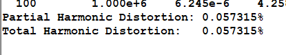
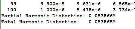
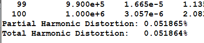
The THD indeed changed when the supply changed. Although the change seems small but it still lowered.If you have a higher voltage transformer to get say 30 - 35VDC, you would increase the headroom as well as decrease THD a little more. Since you only want about 16W, having the extra headroom is always nice when the music has much dynamics.
Attachments
Also, it might not be necessary, but I added a decoupling cap C8 on the load.

When I do not add C8 my bias current or quiescent current on R13 and R14 are not always equal, like for example, current though R13 is 71mA but for R14, it is 68mA or something. However, when I add C8, they have become always equal. I also tested if I should put it near the load (R24) lke the one shown in picture or near the Vo node instead, it has no effect. But I have been told, from a previous post, that C8 could have a high ESR and should affect the Zobel network? So yeah, I added it near R24.
When I do not add C8 my bias current or quiescent current on R13 and R14 are not always equal, like for example, current though R13 is 71mA but for R14, it is 68mA or something. However, when I add C8, they have become always equal. I also tested if I should put it near the load (R24) lke the one shown in picture or near the Vo node instead, it has no effect. But I have been told, from a previous post, that C8 could have a high ESR and should affect the Zobel network? So yeah, I added it near R24.
- Home
- Amplifiers
- Solid State
- Need Help in Designing 3-Stage Discrete Amplifier