I obtained this curve from another site, it's for an Infinity RS 3A. The crossover points are 600Hz and 4kHz. Apparently they're known for eating amplifiers. Full understanding of impedance curves apps a little outside my wheelhouse.
I'm going to modify them to allow biamping - one amp for dual woofers under 600Hz, one for over.
My first thought was to use a Threshold s200 for the bass, the VFET for the rest. But others have advised me to flip that - the VFET for the bass, the threshold for the harder to drive mid/high end.
I believe the threshold is 100W/channel and the VFET 10W/channel. 10W may be a strain for any part of the system.
I thought I'd ask the gurus here, since both amps are Pass pedigree and I trust you guys.
Thoughts?
Barely above 2 ohms at 30Hz? yikes. Better have a good rumble filter on your phono stage.
This is probably not helpful to you, but I've successfully not destroyed my P-channel Sony VFET lottery-adjacent amp driving a couple of strange series crossovers.
This is probably not helpful to you, but I've successfully not destroyed my P-channel Sony VFET lottery-adjacent amp driving a couple of strange series crossovers.
Is the orange line the r component? If so: it doesn’t appear to go below 6 ohms. So not sure why these would eat an amp.
Have seen clipper diodes across old land line telephone receivers. There so if the person at the other end started yelling nothing past a certain voltage got past. Have never seen one across a tweeter until about 10 minutes ago!
Wonder if they are appearing as a short to the rest of the circuit when they get overloaded. They get pretty nasty with harmonic energy which I expect could equate to pushback into the amp.
That's the phase, and it's within +/-60 degrees above 20Hz, but barely. The impedance is basically 2 Ohms at 30Hz and enough reactance to put the phase margin of an amplifier to the test.
At the input to the woofer section we find 600mF of non polar electrolytics (not to be mistaken for uF) followed by 50mH shunted to the return path. This possibly forms a resonant circuit. The Kappas had a bass enhancement switch that closed a circuit like this.
Basically one of the toughest loads an audio amplifier would ever have to drive.

Just to clarify - I didn't create that curve and cannot take credit for it. got it off of another forum.
What would happen with speakers impedance, if one would remove 600mF cap and 50mH inductor?
Still 4.5mH should be enough to cross it to the mid dome.
Still 4.5mH should be enough to cross it to the mid dome.
Basically one of the toughest loads an audio amplifier would ever have to drive.
ugh. I know the threshold can probably do it. what about the VFET? I did hook both up, no biamping, played some music, then did a 20-20kHz sweep for each.
I have an app on my tablet called spectroid that can do some audio analysis. keep in mind this is using the tablet's microphone, a cold sysyem, no speaker placement adjustments or tweaks, etc... I just plugged them in, played a few songs, then the test sweep. the yellow curves are background noise, mainly the hvac, and harmonics I guess. I can always rerun it.
the attachment shows the VFET from 20-20kHz. the threshold s200 has a similar curve.
the dip at 600Hz wasn't there in other runs.

That seems like a very bizarre low freq crossover. What kind of LF driver would require such solution?What would happen with speakers impedance, if one would remove 600mF cap and 50mH inductor?
Still 4.5mH should be enough to cross it to the mid dome.
just hook them (amps) in whichever way you want, and keep arrangement which makes you more happy
VFet is not going to give more than it can ..... it's in fact more safe from going south than amps capable of delivering in short circuit
then think of obtaining speakers capable to make you happy with much lesser power needed
not saying that you need to get rid of Infinity
VFet is not going to give more than it can ..... it's in fact more safe from going south than amps capable of delivering in short circuit
then think of obtaining speakers capable to make you happy with much lesser power needed
not saying that you need to get rid of Infinity
not loud at allThe unanswered question is - how loud do you need it to go?
then think of obtaining speakers capable to make you happy with much lesser power needed
not saying that you need to get rid of Infinity
I just acquired them to replace some efficient full range 🙃
just hook them (amps) in whichever way you want, and keep arrangement which makes you more happy
VFet is not going to give more than it can ..... it's in fact more safe from going south than amps capable of delivering in short circuit
👍😃😃😃👍
I just warmed up the VFET and played for a total of about an hour. Room temp was on the cold side, around 20°.
I measured the temp of the heatsink and the internal bracket that holds the output device. The vfet itself was MUCH hotter than the bracket.
Temp didn't vary much, which surprised me, I thought it would go down, since it's pumping more energy into some difficult speakers.
Heatsink and internal bracket were a steady 41° and 46°. I'm happy with that.
That's the phase, and it's within +/-60 degrees above 20Hz, but barely. The impedance is basically 2 Ohms at 30Hz
Ahh - thanks!
Build an F4 and put it between the Vfet and speakers, problem solved 😁
I don't understand
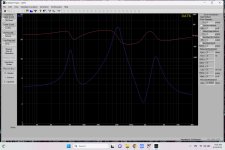
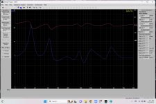
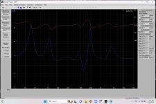
The impedance plot in post #1 doesn't tell the whole story. Infinity only used half of the Lpad's, so the impedance varies depending on where you have the mid and tweeter levels set to. About a month ago, I rescued a pair of RS5B's from the local garbage collection center. It looks like the previous owner had recently refoamed the woofers(quite sloppily). Wondering why they had tossed them, I decided to do some impedance sweeps before hooking them up to any of my electronics. What I found was the impedance was relatively flat with the Lpad's centered but had large dips once the controls were moved off center. When I hooked the speakers up to listen to them, I found the Lpad's to be noisy so I replaced them with fixed resistors. The Lpad's were 5R, so I ordered 2.5R resistors thinking that should be the center of the Lpad and give me a fairly flat impedance. The first pic attached below is the result. A dip down to almost 2R below 2khz. I also own a pair of Kappa 7.1's. The last two pics show the (1)Lpad's centered for a flat-ish impedance and (2) Lpad's turned to arbitrary positions to induce a dip. The Kappa 7.1's impedance doesn't vary as much as the RS5B's in relation to Lpad position. I suspect this has to do with the Kappa 7.1's Lpad's being before the crossover vs the R5B's being after the crossover. All that being said, I have used both pairs of speakers with my Mofo monoblocks and a Technics SE-A7 without issue. I think you'll be just fine
Attachments
- Home
- Amplifiers
- Pass Labs
- How well can the VFET lottery amp handle low impedance?