Hi - I am looking to replace faders on a mixing desk from the early 1980s. They are tired and worn. I'm new at looking at schematics and would really appreciate your help and expertise on replacements.
The current faders are 88mm long with 60mm fader movement and are 10K B (which I think is a linear fader). They have been swapped out at some point (tell tale signs of additional screw holes a few mms below the top screw hole).
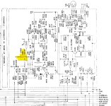
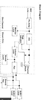
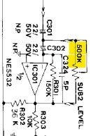
I think the schematic suggests 5K B faders (but as a newbie I'm not sure if I am even looking at the correct part of the schematic!?). I have included a block channel diagram and the schematic for the channel (highlighting where I think the fader is located).
My questions are - am I on the right track? And if so, is it best to put in 5K B faders as per the schematic? Or are there advantages or draw backs with going with 10K B. Or is logarithmic (Audio) taper instead of the linear (B) fader? Any recommendations for faders? Thanks so much for help.
The current faders are 88mm long with 60mm fader movement and are 10K B (which I think is a linear fader). They have been swapped out at some point (tell tale signs of additional screw holes a few mms below the top screw hole).
I think the schematic suggests 5K B faders (but as a newbie I'm not sure if I am even looking at the correct part of the schematic!?). I have included a block channel diagram and the schematic for the channel (highlighting where I think the fader is located).
My questions are - am I on the right track? And if so, is it best to put in 5K B faders as per the schematic? Or are there advantages or draw backs with going with 10K B. Or is logarithmic (Audio) taper instead of the linear (B) fader? Any recommendations for faders? Thanks so much for help.
Attachments
Thanks so much Citizen124032 for your advice - really appreciate it. And for the tip about posting the schematic image upright next time.
Because I am new to this - any tips on how I tell, from the schematic, that it is a logarithmic rather than a linear fader? Is that what the ‘B’ means or is the application of it being in an audio mixer that suggests a logarithmic rather than linear taper?
Because I am new to this - any tips on how I tell, from the schematic, that it is a logarithmic rather than a linear fader? Is that what the ‘B’ means or is the application of it being in an audio mixer that suggests a logarithmic rather than linear taper?
According to this article, the meaning of 'A' and 'B' varies according to location : https://eepower.com/resistor-guide/resistor-types/potentiometer-taper/#
According to the table in that article, A can either mean linear or logarithmic, but B is always linear. Then again, a fader is a kind of volume control and those are normally logarithmic.
Looking at the other potmeters in the circuit, they appear to be using the American code. The gain control in the microphone amplifier, which should be antilogarithmic, is marked 10KC and the ones in the Baxandall tone control, which should be linear, B100K, except the bottom one, which is marked 500KW, whatever that may mean. The pan pot, which definitely has to be linear, is 25KB.
It looks to me like they preferred a linear taper for the faders. In the local radio station here, the lower parts of fader potmeters frequently got damaged because when fading out, DJs would reduce the level slowly at first and then suddenly slam the fader to 0 (- infinite dB). They wouldn't have to do that with linear faders.
When you put one of the present faders halfway, are the resistances from the wiper to the ends about the same? More importantly, do you like slow fade-outs or slow at first and then fast?
Thanks for sharing this article. It was a useful read. And the table was informative too.According to this article, the meaning of 'A' and 'B' varies according to location : https://eepower.com/resistor-guide/resistor-types/potentiometer-taper/#
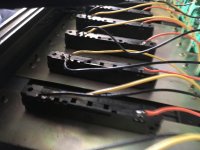
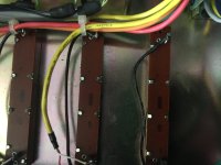
Really appreciate the analysis of the schematic. Thank you. The current channel faders (which aren’t the originals) are radiohm 10K B (pictured in the desk). Unsure if they are linear or audio taper. But will try your suggestion when back in front of the console.It looks to me like they preferred a linear taper for the faders.
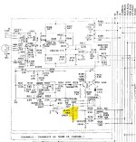
In terms of the 500KA. The master fader and sub faders have 500KA printed on the bottom. Also pictured in the desk.
Attachments
Thanks Mark. Yes I was surprised to see 500K. The console runs pretty quietly. I looked at the master section of the schematic it has 500k on those faders. There is a resistor (not sure what size/value) wired to each of 3 of the four faders in the master out section. I couldn’t immediately see any resistor or resistor value in the schematic. The one without the resistor (main out right) has a stronger output (bit louder) but to my ears sound fine. However at present i have to increase vol the main out left to compensate!
Attachments
Last edited:
- Home
- Design & Build
- Parts
- Help with potentiometer on this schematic please