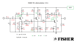
Hi! there is a similar design of such a 4 transistor phono preamp, in the Dual CV1400. The main difference to the elektor schematic is, that the Dual uses 2
voltages +/-15V supply, and the elektor needs 20-24V .
With the help of a Dual board forum colleague, he milled the circuit boards, I build a CV1400 clone. It works good, but Iam curious about the elektor circuit, maybe one day I will build it.
best regads Armin
voltages +/-15V supply, and the elektor needs 20-24V .
With the help of a Dual board forum colleague, he milled the circuit boards, I build a CV1400 clone. It works good, but Iam curious about the elektor circuit, maybe one day I will build it.
best regads Armin
Attachments

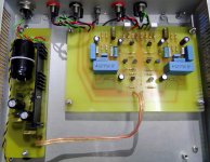
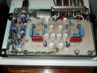
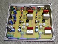
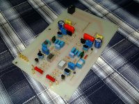
Hello ! A year ago, I assembled a PreConsonant phono-preamp (on BC-559/BC549 transistors manufactured by Motorola). It works well and the noise level is small . But I changed the nominal value of the 270 ohm resistor - set 130 ohms . I got the boost I needed . The sound is good .......This year I made another version of this preamp - on germanium transistors . The germanium variant of course has more noise than silicon . But it sounds good . In the photo - silicon PreConsonant and germanium ..... P.S.- For the germanium version , we had to change the ratings of several resistors in the circuit ...my 50Cents..
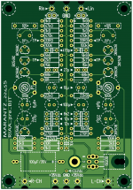
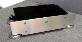
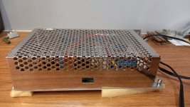
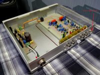
Build for an Marantz 2245.
state: build and still beta-state..it's too noisy.
Attachments
Last edited:
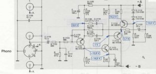
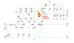
There is no mistake . There is a separating capacitor in front of the potentiometer .As drawn the volume control is coupled directly to the +12V DC power supply. That might be a mistake. Maybe the draftsman accidentally omitted a resistor from the schematic drawing?
_
So you have (DC voltage source) ---> (coupling capacitor) ---> (potentiometer) ---> output.
The DC voltage source has, by definition, no signal. It's pure DC with zero nanovolts of superimposed AC. So there is no AC signal applied to the coupling capacitor and there is no AC signal applied to the potentiometer and there is no AC signal at the output.
The DC voltage source has, by definition, no signal. It's pure DC with zero nanovolts of superimposed AC. So there is no AC signal applied to the coupling capacitor and there is no AC signal applied to the potentiometer and there is no AC signal at the output.
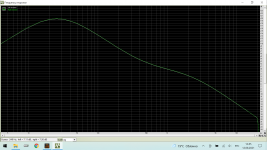
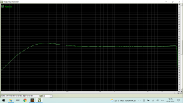
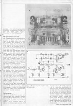
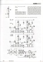
I have this Elektor circuit working . Here are his charts - RIAA and reverse-RIAA . Pay attention to the date of these measurements at the bottom of the screen - this preamp has been working for more than a year . Elektor produced this preamp as a KIT . This is a well - known and working scheme of 1978 .So you have (DC voltage source) ---> (coupling capacitor) ---> (potentiometer) ---> output.
The DC voltage source has, by definition, no signal. It's pure DC with zero nanovolts of superimposed AC. So there is no AC signal applied to the coupling capacitor and there is no AC signal applied to the potentiometer and there is no AC signal at the output.
Attachments
I owe you an apology, @vsmusic !! My comments in #63 and #66 were incorrect and I'm sorry for wasting your time with them.
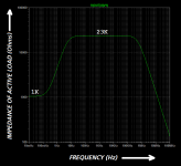
My analysis of your "T12" subcircuit was completely wrong; I felt T12 was a 24VDC to 12VDC power supply smoother (capacitance multiplier), with very low output impedance. NOPE! In fact it is a high impedance active load for T3. Simulator output attached. So the output signal at T3 emitter is not shunted to AC ground by an ultra low impedance power supply as I thought; T3 is just a regular emitter follower with an active load. Please disregard my ignominious blunders.
_
Attachments
That's clearly the unlucky resistor R13 missing there.As drawn the volume control is coupled directly to the +12V DC power supply. That might be a mistake. Maybe the draftsman accidentally omitted a resistor from the schematic drawing?
_
Or the circuit would not reproduce any sound.
Hello Mark ! We can all make mistakes , and there is nothing irreparable in this . This scheme looks a bit unusual , but it works well . Here is a short video . Unfortunately , it 's not mine , I 'm a little lazy for such filming . But it was the video of this person that aroused my interest in this scheme - it shows the work of this phono-preamp.I owe you an apology, @vsmusic !! My comments in #63 and #66 were incorrect and I'm sorry for wasting your time with them.
My analysis of your "T12" subcircuit was completely wrong; I felt T12 was a 24VDC to 12VDC power supply smoother (capacitance multiplier), with very low output impedance. NOPE! In fact it is a high impedance active load for T3. Simulator output attached. So the output signal at T3 emitter is not shunted to AC ground by an ultra low impedance power supply as I thought; T3 is just a regular emitter follower with an active load. Please disregard my ignominious blunders.
_
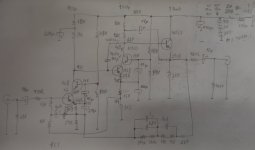
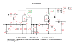
If people want to play with cascoded germanium, here is a circuit that I've made, with excellent results, sonically and technically.
Now the pre was with a friend of mine and he is very happy! Far better (in his words) than other preamps he tested against, including commercial ones.
I recommend!
PS.: the input bootstrap 4u7 capacitor needs to be at 390R side (my drawing here show options).
Now the pre was with a friend of mine and he is very happy! Far better (in his words) than other preamps he tested against, including commercial ones.
I recommend!
PS.: the input bootstrap 4u7 capacitor needs to be at 390R side (my drawing here show options).
Attachments
If people want to play with cascoded germanium, here is a circuit that I've made, with excellent results, sonically and technically.
Is a phono pre for MM or high output cartridges, near or higher than 2mV recommended.Now the pre was with a friend of mine and he is very happy! Far better (in his words) than other preamps he tested against, including commercial ones.
I recommend!
PS.: the input bootstrap 4u7 capacitor needs to be at 390R side (my drawing here show options).
What about the original Pass Pearl? https://www.passdiy.com/pdf/pearlphono.pdf
It is rather simple, although I think that the power supply voltage drop is too generous.
It is rather simple, although I think that the power supply voltage drop is too generous.
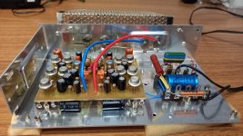
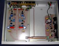
2 years ago I built phono preamp on J-FET (manufactured by Toshiba). The scheme is taken from the publication Elektor ( 2004/1 ) . But I used other transistors , changed the bias circuit of the first stage , and the ratings of some resistors . This preamp sounds very good , and has a very low noise level .
Attachments
But the input impedance is 100k, not the standard 47k... Yes, 2SK170's are quiet! I think they are unobtainium now though?
On the back wall of the preamp , I installed an input resistance switch ( 47k or 100k ) . I need the 100k mode to work with some cartridges ( with high inductance coils ) .But the input impedance is 100k, not the standard 47k... Yes, 2SK170's are quiet! I think they are unobtainium now though?
Attachments
- Home
- Source & Line
- Analogue Source
- Discrete phono stage, single supply.