If I move the driver to 1/3(x ~end correction) and ‘remove’ the 3/4 harmonic does it also ‘remove’ the 9/4,15,21,27,33….
(Hypothetically)?
(Hypothetically)?
Booger,
I haven't worked on TL's in awhile, so I'm a little rusty. But I just ran a few quick sims with LATL and that's exactly how it seems to work. Every third resonance is "removed". Seems to work the same with a tapered TL, but not an MLTL.
Hope that helps, and that someone corrects me if I'm wrong!
Eric

Thanks Eric 🙏🏻I think I find the same in a raw simulation (undamped, so I can notice specific freq)?.
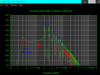
300(1/4)
100(3/4)
33.33(9/4)
20(15/4)
14.2857(21/4)
and so on
i wonder why people would put the driver Elsewhere (@ ~5/4 or ?) after observing this .
300(1/4)
100(3/4)
33.33(9/4)
20(15/4)
14.2857(21/4)
and so on
i wonder why people would put the driver Elsewhere (@ ~5/4 or ?) after observing this .
Attachments
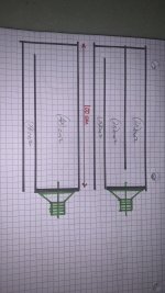
This opened another can of worms to simulate …. How are they different?
One creates a pipe mode, but resolves it (by driver entry) and the other is the same exact volume 😝and essentially avoids the pipe resonance
(I’m so confused 😕)
One creates a pipe mode, but resolves it (by driver entry) and the other is the same exact volume 😝and essentially avoids the pipe resonance
(I’m so confused 😕)
Attachments
Last edited:
Some possible reasons:i wonder why people would put the driver Elsewhere (@ ~5/4 or ?) after observing this .
- between .2 and .33 minimizes both modes.
- higher (closer to 0.2) can be closer to ear height
- higher might look "more right" to some
- damping mitigates the peaks too, so perhaps perfect driver placement is less critical than it seems.
Eric
I can hardly read on my laptop as my eyes are shot and it's 0320 local time, but they're fundamentally different pipe geometries. The first is an end-loaded tapered pipe, the second is a tapered pipe that is 33.3% longer with the same percentage (more or less) tap location for the driver; it will be tuned lower in QW terms though provide reduced gain since Vb is unchanged, with the usual effects you'd expect with a 1/3 driver offset in addition to that.This opened another can of worms to simulate …. How are they different?
For a straigt pipe the harmonics are were they "should be" according to gemetry. If the pipe is flared and/or folded things start to shift around. Folding a pipe once wiith equal length of the two sections is far better at supressing odd harmonics than an "IMF style " fold. I can add some measurment later from Tyrland.
Notes
First pipe fundamental at 40 Hz third at 120 Hz and 5th at 200 Hz
Negative taper: Lower the fundamental a lot but frequencies of harmonics unchanged
Negative taper and one fold: Fundamental little change 3rd and 5ht supressed about 10 dB
Negative taper and "IMF" double fold: Fundamental as the one with one fold but harmonics even worse than the unfolded one!
My take is that a good start would be starting with a pipe & driver geometry that is intrinsically good and then finish the design with some damping material. This in contrast to starting with a geometry that has sever problems with harmonics and then have to use a lot of tricks to save it.
- Home
- Loudspeakers
- Full Range
- TL resonances