This is for compression driver, forgot to mention 🙂Cool. 😎
A couple of thoughts and questions... Where did you get the waveguide data, is it measured from a a tweeter in a waveguide, or is it simulated?
Do you have in mind a particular tweeter that can be crossed as low as 1.1k ? Even with a lot of waveguide gain, that seems a bit sporty for most tweeters. A Bliesma T34B might do it. There are a couple of ScanSpeaks and Morels that might do it. Thoughts?
J.
Since everything relates to wavelength all the DI and polarmap stuff would have similar features if the system was scaled.
If the experiment was repeated with 13cm waveguide, 3", 4" and 5" drivers, 2.2kHz crossover and 17cm c-c spacing, the graphs would look about the same but everything in the graphs moves an octave higher up in frequency.
Similarly, 52cm waveguide with 12", 16", 20" woofers, 550Hz crossover and 64cm c-c would get results an octave lower in frequency.
Last edited:
Just thinking out loud here...
Correct me if wrong, but if the size of a woofer dictates the frequency of beaming by cancelation and phase in the membrane itself. Could it then be a possibility, that a larger CTC kinda imitates the acoustical output of a larger driver - even when it's not - hereby resulting in a smoother DI?
Correct me if wrong, but if the size of a woofer dictates the frequency of beaming by cancelation and phase in the membrane itself. Could it then be a possibility, that a larger CTC kinda imitates the acoustical output of a larger driver - even when it's not - hereby resulting in a smoother DI?
Well, kind of, if you had two woofers like in MTM their (vertical) DI would be similar to one big woofer similar in size, response starts narrowing at wavelength that relates to size of (combined) transducer. But, there is no output on the middle of two drivers so the response is not exactly a beam as it doesn't average out like with single big transducer. You can imagine transducer (a cone) like so: every point on the cone is source of spherical sound wave, and there are infinitely many. Simplify thinking by imagining only few points, perhaps one on each side of the cone and think about their path length difference to any particular observation angle.
In case of tweeter + mid system the effect of c-c is a bit different because they have only small overlapping bandwidth, while single driver or MTM woofer bandwidths would overlap completely. Even though you can imagine tweeter and mid at crossover as "one physical combined object" its only true where their bandwidth overlap. I mean, even if both had exactly same smooth DI the system DI would differ from this if there is interference.
Even if both tweeter and woofer were ideal and had DI = 0, they would make interference around crossover for some bandwidth, depending on c-c and wavelength. As long as there is (significant) destructive interference combined DI is something else than either individual DI.
DI is difference between axial response and total power emitted. Hump in DI means total power is low compared to axial response. In case of crossover and two sources interfering its the destructive interference that destroys power, DI gets a hump.
To make a power loss/DI hump go away we need to reduce destructive interference off the two transducers.
Strong destructive interference happens when: interfering sounds are equally loud and exactly opposite phase. Opposite phase happens when path length difference is 1/2wl and exactly as loud happens when individual DIs match toward the angle we have 1/2wl path length difference (c-c, so 90 deg).
Several ways to affect this: reduce level of either = mismatch on individual transducer DI, or keep max path length difference (c-c) less than 1/2wl = the 1/4wl rule of thumb for point source. Third way is the increased c-c. When we have c-c past 1wl then there relatively more constructive interference than destructive interference between 0 and 90 deg. There can be side-effects, what happens to horizontal DI?🙂
Last edited:

@tmuikku
Great write-up thank you 🤓
Right now, I play with a midrange/tweeter combo, that consist of a MW13TX and SB26ADC in 5" Augerpro WG. My initial thought when going for this design, was that the TX woofer has a clean, smooth off-axis as frequency goes up - very fitting for how the ADC acts in the 5" WG. So around 2000Hz, the beaming of the TX, fits quite smoothly with the beaming of the WG, resulting in that smooth tilt downwards, as frequency goes up.
CTC is around 140mm and the WL at 2000Hz is around 173mm. 140/173 is around 0,8 WL at cross-over. And I read somewhere that I should be close to 0,75.
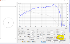
I do not know how to make a DI graph. But I measure on-axis and a few steps off-axis. Get something like the following and find it very smooth, detailed and neutral sounding. It's gated around 3-4ms and at 0, 15 and 45 degrees. Gotta make a more precise measuring setup, so that everything match up better. But I feel that I'm on the right path. I measure with a calibrated microphone from cross-spectrum, and the sound card and measuring software, uses loop-back for correct phase.

I tend to focus on the horizontal plane, since this is where we are most sensitive with timing errors and reflections. We have more or less the same distance to our ears in the vertical plane, and therefore we should be able to live better with this compromise. I only truly see a great horizontal + vertical DI - with Coax... and that introduces new challenges 😊
Great write-up thank you 🤓
Right now, I play with a midrange/tweeter combo, that consist of a MW13TX and SB26ADC in 5" Augerpro WG. My initial thought when going for this design, was that the TX woofer has a clean, smooth off-axis as frequency goes up - very fitting for how the ADC acts in the 5" WG. So around 2000Hz, the beaming of the TX, fits quite smoothly with the beaming of the WG, resulting in that smooth tilt downwards, as frequency goes up.
CTC is around 140mm and the WL at 2000Hz is around 173mm. 140/173 is around 0,8 WL at cross-over. And I read somewhere that I should be close to 0,75.
I do not know how to make a DI graph. But I measure on-axis and a few steps off-axis. Get something like the following and find it very smooth, detailed and neutral sounding. It's gated around 3-4ms and at 0, 15 and 45 degrees. Gotta make a more precise measuring setup, so that everything match up better. But I feel that I'm on the right path. I measure with a calibrated microphone from cross-spectrum, and the sound card and measuring software, uses loop-back for correct phase.
I tend to focus on the horizontal plane, since this is where we are most sensitive with timing errors and reflections. We have more or less the same distance to our ears in the vertical plane, and therefore we should be able to live better with this compromise. I only truly see a great horizontal + vertical DI - with Coax... and that introduces new challenges 😊
It should be logical than the MTM mimics the diameter of a standalone bigger driver vertically but is it also for horizontal beaming ? Is it not the purpose of an array to narrow the spread (horizontally) to focus the power in a littlier "window" ? Noticicabily if the width of the baffle is close to the width of the M used in the MTM !
Hi, I'm not sure if I understood, but yeah the MTM mids can be thought to be kind of a short array. Array has narrow coverage on the long axis, and wide coverae on short axis. Narrowing is due to interference, which relates to length of the array and wavelength.
Simplified,
-10cm long sound source (array) has narrowing coverage roughly 10cm and shorter wavelength, 3.4kHz and up.
-100cm long array would have narrowing coverage from roughly 100cm and shorter wavelength, 340Hz and up.
So, if array is 10cm wide and 100cm tall, horizontal coverage will be wide up to 10cm frequency and vertical coverage will be wide only up to 100cm frequency. "focus", narrower coverage, happens on the long axis.
1cm wide, 10cm tall ribbon tweeter would have very wide horizontal coverage up to 20kHz, but very narrow vertical coverage, especially on the top octave. 20kHz sound wavelength is 1.7cm.
Last edited:
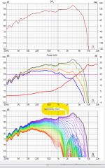
Here simple 1, 2, 3 and 10 driver vertical arrays. Driver is ~10cm ideal driver for simplicity, baffle stays the same 10x100cm. As sound source is elongated vertically, vertical coverage narrows from lower frequency all the way up, while horizontal coverage stays roughly the same.


If you refer these to previous post simple example, eyeballing these results 10cm wide (ideal) source is roughly omni up to about 20cm wl, 1.7kHz, or 40cm depending which color one is looking at 😀 Either way, at 1wl around 3.4kHz coverage is already quite narrow, roughly 90deg nominal coverage.
Here two drivers spaced apart. Array length is similar with 3 drivers, but now using only two as in MTM

100cm tall "array", with two drivers only.

Three drivers

How about 10x100cm ideal rectangular transducer?

If you refer these to previous post simple example, eyeballing these results 10cm wide (ideal) source is roughly omni up to about 20cm wl, 1.7kHz, or 40cm depending which color one is looking at 😀 Either way, at 1wl around 3.4kHz coverage is already quite narrow, roughly 90deg nominal coverage.
Here two drivers spaced apart. Array length is similar with 3 drivers, but now using only two as in MTM
100cm tall "array", with two drivers only.
Three drivers
How about 10x100cm ideal rectangular transducer?
Last edited:
oval-ish like the old green Saba, but flipped in the vertical direction (sorta like makes SCANSPEAK with its new non affordable cat's eye drivers)
Maybe two oval-ish verticaly i a MTM could make sense after all if the C to C is still manageable ? 1.2 WL something around 2K hz because of the higher distance with the center (I mean when the oval-ish is flipped with its greater size in vertical area)
Maybe two oval-ish verticaly i a MTM could make sense after all if the C to C is still manageable ? 1.2 WL something around 2K hz because of the higher distance with the center (I mean when the oval-ish is flipped with its greater size in vertical area)
Edit time over.
All of the above examples have listening height at the mid of the array, at 50cm mark. What if listening height was varied? do we get any sound because the vertical seems to beam? Lets use the last ideal rectangle.
Yes we do get sound, notice the vertical coverage stays roughly the same despite it being normalized graph, up until we observe at very end of the array height.


I think the vertical polar map leads to astray a bit, because its drawn/computed for particular observation point (height and distance) and not as a balloon considering all listening heights:
the array is not curved physically or with delay, all drivers emit sound at the same time. Sound from driver that is at same height to ear arrives first because its physically the closest one. Shortly after arrives sound from first drivers above and below, and so on. On a 100cm long array, listened at mid height 2m away with 10cm driver spacing we get same sound to our ear every: 200 - sqrt(200^2 + 10^2) ~= 2.5mm apart about five times. Or so 🙂 Actually the spacing spreads out if there is no shading / curvature with the array, 5th driver is ~6.2cm further away acoustically, simple pythagoran math. If listening at the end of the array there is more drivers only to the other direction, only below or above, furthest one being quite far ~20cm away, and different interference pattern emerges.
All of the above examples have listening height at the mid of the array, at 50cm mark. What if listening height was varied? do we get any sound because the vertical seems to beam? Lets use the last ideal rectangle.
Yes we do get sound, notice the vertical coverage stays roughly the same despite it being normalized graph, up until we observe at very end of the array height.
I think the vertical polar map leads to astray a bit, because its drawn/computed for particular observation point (height and distance) and not as a balloon considering all listening heights:
the array is not curved physically or with delay, all drivers emit sound at the same time. Sound from driver that is at same height to ear arrives first because its physically the closest one. Shortly after arrives sound from first drivers above and below, and so on. On a 100cm long array, listened at mid height 2m away with 10cm driver spacing we get same sound to our ear every: 200 - sqrt(200^2 + 10^2) ~= 2.5mm apart about five times. Or so 🙂 Actually the spacing spreads out if there is no shading / curvature with the array, 5th driver is ~6.2cm further away acoustically, simple pythagoran math. If listening at the end of the array there is more drivers only to the other direction, only below or above, furthest one being quite far ~20cm away, and different interference pattern emerges.
Last edited:
Perhaps, but the tweeter comes in with different pattern?oval-ish like the old green Saba, but flipped in the vertical direction (sorta like makes SCANSPEAK with its new non affordable cat's eye drivers)
Maybe two oval-ish verticaly i a MTM could make sense after all if the C to C is still manageable ? 1.2 WL something around 2K hz because of the higher distance with the center (I mean when the oval-ish is flipped with its greater size in vertical area)
I think I've never heard MTM speaker, hopefully someone corrects if the following is off based: to me MTM system don't seem to make much sense without more ways, like wmtmw. Because, the two mids seem to make only about octave wide narrow pattern, associated elevated DI for the octave. Kind of vertical lobes that a crossover in typical MT speaker already does, with even order filters. Then crossed over to a tweeter that physically fits in between somehow, comes in with different pattern and we have a kink in DI. Perhaps if the vertical narrowing is at some very important frequency band so that perceived audio quality gets better? Perhaps the narrowing extends two octaves, first one below xo due to c-c and another octave due to xo? I dunno how it works, or why people would do MTM speakers. Perhaps for some other reasons than what I can think of. Marketing department probably comes up with many reasons.
Last edited:
The only advantage I can see it the use of mid driver that has not enough sensivity so needs to be doubled and or for the same reason a specialised mid that has short voice coil Xmax that has not enough headroom to follow the spl of the woof and tweeter at higher volume and dynamic peaks.
Yeah thats one thing, sometimes could be good and fine option. But the drivers could be in TMM as well, is it better or worse and why? Why not use bigger driver or one with better xmax? These are limitations for design and as such could be viewed as compromise for audio quality. Perhaps there is some valid reason as well, to use MTM, that relates to hearing system / rooms? perhaps the graphs lead astray?
Last edited:
Sorry for the newb question but then diffraction tool is only generating angles from +/-90 degree on export. It there a way to increase this to +/-180 degrees?
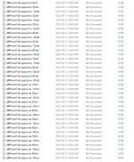
Hi, are you sure? I think it exports it all, see filenames it exports. If the main window graphs show only 90deg right click on the graph and untick the 90deg limit
The export folder that the export dumps into only contains +/-90 degrees. I say only in that it would be nice to get 180 degrees but greatful for the existing functionality. I'll check my other machine but I think it does export +/-180 degrees, but I can't find a place to set this.
Thanks,
Thanks,
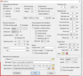
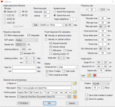
Use the "full space" option:Sorry for the newb question but then diffraction tool is only generating angles from +/-90 degree on export. It there a way to increase this to +/-180 degrees?
Attachments
Thanks, Draki. I've done this but still in the export folder I only get values to +/-90 degrees. This is in the export folder, not a show only 90 degree setting in the DI graph. Seems like there are some machines that do 180 degrees and some that do 90 degrees. Can you show your tools options settings? These are mine. Thanks,
Attachments

- Home
- Loudspeakers
- Multi-Way
- VituixCad Simulations with Ideal Drivers