You could, looking at the chart I provided you dont need much more than 47 ohms to be up to 50mA idle.Excellent, thank you very much. Can i use 100R pot for R21? For output transistors i have to-247 package so i guess one pair will be enough for +/-25vDC rails.
I would also like to try your version (post 17), have all required transistors for that.
Thanks & Regards
Which is way to high for thermal tracking with diodes.
but if you added more output pairs your capable of getting bias that high for a pair
So its up to you how you wanna monitor bias and adjust it.
if a set resistor, and real world voltages when you build it. you could use a set resistor at
10 ohms then 15 , 20 or 22 to get around 1 to 6 mV drop across R6
This amplifier is mainly good towards low bias since the diodes dont thermal track well.
eventually as the amp heats up it will have higher bias. at 20 to 35mA
typical design would start at 20 to 30 mA and as it heats up, better thermal tracking
would keep that from climbing.
the design had no bias or very little, I just like things to be slightly on, which is why I
added the resistor. to get around 3 to 6 mA idle current
You could start off at around 18mA, but would defiantly need to mount the diodes
with thermal contact to the heatsink near the transistors.
with a 100 ohm pot it could be parallel with another resistor. so it wont jump up bias
if you turned it to 100 ohms. Being 47 ohms is too high a 100 ohm pot could be jumpy.
So in parallel to another resistor 82 ohms, from 10% to 100% rotation.
would be 9 to 45 ish ohms. Instead of jumping up to to 100 with
just the pot.

Peter Baxandall slightly preferred using a diode-connected transistor (collector connected to the base) over a real diode as the Baxandall diode, by the way. It results in better distortion compensation because it has an emission coefficient closer to 1 than a real diode. See Baxandall and Self on audio power page 95.
By taking into account what John said i think it's better to use VBE multiplier instead of diode string because component count is the sameYou could, looking at the chart I provided you dont need much more than 47 ohms to be up to 50mA idle.
Which is way to high for thermal tracking with diodes....
 , also mounting diodes close to heatsink is a pain. What should be the proper value of resistor & preset (VBE multiplier) for this? I think you also have to change couple of resistor values for that. Anyways your help would be greatly appreciated.
Thanks & Regards
Last edited:
Well, the circuit you've posted is not really a complete solution and may be slightly worse than either of the options I mentioned.
This is because you have now eliminated the 4.7 ohm resistor in series with the diode, whcih actually helps with bias stability especially when using a diode string. You could put that resistor back as well as keeping the 47 ohm in parallel with the diode.
Strings of diodes which are not mounted next to the transistors they are supposed to be monitoring will not control the quiescent current very well. You can set the current low but after powering signals, warming the transistors, the current will creep up.
Better to add a 0.22 ohm resistor in the collector of the lower NPN, as mentioned, so that there is at least some additional voltage feedback.
And, use a Vbe multiplier rather than a string of diodes. Diodes for the bias network were out of favour decades ago!
@MarcelvdG - yes, Baxandall might have said to use a diode connected transistor. Of course, complementary pairs are not exact complements due to the differences between N and P material. In practice, a diode (rather than a diode connected transistor) won't be an exact match either and are likely to be worse as diodes generally have different ideality factors from transistors as Marcel noted, but diodes have been frequently used and provide at least some degree of symmetry.
Another option, if you are prepared to leave out the Baxandall diode, is to add a 0.22 ohm resistor in series with the lower NPN transistor, but connect the 4.7 ohm from the PNP driver emitter to the collector as well. This increases the bias voltage needed and will porbably allow the original three diode string to be used as the bias, and any voltage across the NPN resistor (47ohms) will be reflected across the 4.7 ohm (by one tenth, obviously) which adds a little stability (but only if the diodes are thermally tracking the output). Secondly the additional 0.22 ohm resistor is now in a feedback loop which helps to control the current.
Finally, again, if you are concerned about the addition of a third "emitter resistor" you can omit the original one in the emitter of the NPN unless you are planning to parallel transistors.
It's really a matter of how well you want to limit crossover distortion.
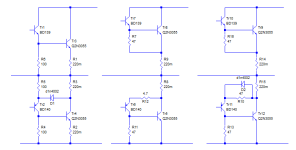
Just simplified modelBy taking into account what John said i think it's better to use VBE multiplier instead of diode string because component count is the same
View attachment 1163282
Thanks & Regards
to show output stage and VBE
R24 could be 100 ohm pot
So at mid rotation it should be biased around 30mA
of course being 100 ohms would be adjustable to about 3mA to 140mA
but basically the pot centered should be close to range when you adjust.
as with the Quasi output section
there is numerous ways to configure the emitter resistors for output transistors
John has mentioned a few.
Since we dont have VI limiters, I just put them on the emitters
otherwise for current sense triggers etc etc the resistor positions are changed.
Can i use VBE part of your simplified schema for this without changing anything except diode string?Just simplified model
to show output stage and VBE
R24 could be 100 ohm pot
So at mid rotation it should be biased around 30mA....
View attachment 1163305

The configuration is wrong. That is, it isn't the way to make a pseudo-darlington properly. Take a look at the old Naim outputs (yours uses 47 ohm and .27 ohm which is ok):

Differential was bugging me.
Same part count changed topology slightly.
Outputs slow enough minimal Degeneration
Makes it very stable at 22 K
Added VBE
Bias shown 22 mA at 22C will raise to around 30mA to 33mA at higher op temps


Same part count changed topology slightly.
Outputs slow enough minimal Degeneration
Makes it very stable at 22 K
Added VBE
Bias shown 22 mA at 22C will raise to around 30mA to 33mA at higher op temps
That illustrates the standard quasi-complementary output stage I've been discussing.
I would suggest it is a universal standard now.
The configuration WhiteDragon keeps posting is not ideal.
I would suggest it is a universal standard now.
The configuration WhiteDragon keeps posting is not ideal.
For the most part agree.
There is no VI limiter, so placing resistors as shown post #32 would be necessary
for current limiting / short circuit protection
Im just placing resistors on emitters for thermal stability.
If you wanted current limit, then a more " symmetrical" placement
of resistors is necessary. Then I will still add additional emitter resistors.
More helpful with multiple output devices
Last edited:
You could use the spare diodes from the previous bias generator to provide current limiting short circuit protection!
- Home
- Amplifiers
- Solid State
- Baxandall diode in QC amp