Do we really need baxandall diode there? Some people strongly recommends it for better HF linearity but the designer says D1 isn't necessary & i can use this amp without it (but i'm still confused because he used that diode in the original design but now telling me not to use it).
Attachments
Last edited:
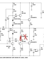
I thought a Baxandall diode was supposed to be connected between the feedback point of a CFP stage and the output, that is, not like it is connected here.

I thought it is baxandall but without a parallel resistor & capacitor like used in many quasi complimentary amps.
Diode has same effect.
to balance the output stage.
majority of AC current can go to one output transistor without it.
and non linearity will be seen at clipping
Diode will fix both issues.
If the circuit values are designed correctly.
otherwise a old trick without diode was to keep bias extremely low
towards class B
to balance the amplifier. But as usual crossover distortion is
high.
Darlington has 2 diode drops, Feedback pair one drop.
Their is numerous circuits to achieve the same result.
So the amp can be biased correctly into class AB and
not have majority of AC current go to one output transistor.
Last edited:

Very basic straight forward amplifier.
Will work though, some changes could be made.
But dont wanna nit pick design.
Because whenever fun simple projects get posted.
Everyone wants to add 50 more parts to a working design.
few minor things
C1 bootstrap capacitor could be larger 100u
R5 seems rather high.
looking at the differential input design.
I think he had hard time getting amplifier
DC offset to center.
so * R5 is rather high to balance amplifier.
otherwise is working design
this amplifier thermal tracks with diodes.
most people will scream and whine about them.
Be fine, just think it needs potentiometer so
you can still adjust.
Q4 is BD139 needs high current to drive.
Looking at R2 , R3 my guess is 1.5K to high
need lower value to drive second gain stage.
Likely why amplifier had so much DC offset.
* R5 was made too high to compensate.
Last edited:
I think Q5 and Q7 only kick in when there is a signal larger than some threshold, that they have essentially zero quiescent current.
The amplifier needs three diode drops for bias.
And that is provided.
2x 4007 being used will have higher drop when cold
not trying to be argumentative but seems at a glance
amplifier is biased to AB not B and could be on higher side.
Which brings good point to original question.
When baxandall diode is used, bias voltage needed is different.
So if removed then amplifier bias would jump.
just think minor change would be adding adjustable pot
otherwise the preset value set for bias was likely designed
to have diode. so removing baxandall diode cause changes
to bias.
Is simple fun amp.
Might as well simulate for fun
To do DC and AC analysis
Then question can be fully answered
And show examples of how removing
and using Baxandall
diode actually effects amplifier.
Then likely fix DC offset issue.
I can simulate, likely wont make part
numbers same. But replicate
same parts and voltages shown.
Actually yes correct.As drawn in post #7, you need four diode drops for the output transistors to turn on, as you need to bias Q3, Q5, Q6 and D1.
4 diodes needed with baxandall drop.
So was my concern, and forgot design using 4 diodes
if baxandall is removed, bias jumps.
With 3 diodes depending on temp
outputs may be around 3 to 9ma at most.
thermal tracking less concern
if bias very low.
DC analysis
Current sources Reasonable Values,
Likely Current increase for AM3 or second gain stage T4 would like higher 8 or 10mA
instead of 5.5mA
And Correct is Low bias Class B
AM1 , AM2 for the most part are off.
If you look at output VF1, DC offset is high around 89 mV
So the overall positive offset is making T5 slightly on @ 3mA
If you did AC analysis most the current would be on AM1.
I think few simple value changes would get DC offset on output down to more normal 10 mV or lower.
Class B is fine but T7 not on at all.
Think would be good to balance amplifier and get both outputs slightly on around 3 to 6mA
As mentioned with Quasi important to balance DC otherwise
either T5 or T7 would take most the AC load
this case T5 take most the load with offset positive.
I test the amp with around 11 volt output or around 16 to 17 watts
you can see in AC analysis most current goes to T5
of course over time would change with temp, all Semi shown at 22 C

AC analysis
interesting with bootstrap R4 / R9 you see current rise a little with
more signal from 5.5 to 6.7 mA

THD1 or 1K 17 watts to 8 ohm .2%
Maybe improve if diff current raised to 2mA
and second stage to 8mA

Can click image for larger Harmonic profile.
It does have pretty strong second harmonic
and out of phase. Upper harmonics in phase.
likely the Class B make highend possible scratchy
Most Second Harmonic likely not very Linear BD139
and bootstrap. I have done this on purpose with
MI amps. To make amp more 2nd Harmonic
Simple amps can be Fun.

Current sources Reasonable Values,
Likely Current increase for AM3 or second gain stage T4 would like higher 8 or 10mA
instead of 5.5mA
And Correct is Low bias Class B
AM1 , AM2 for the most part are off.
If you look at output VF1, DC offset is high around 89 mV
So the overall positive offset is making T5 slightly on @ 3mA
If you did AC analysis most the current would be on AM1.
I think few simple value changes would get DC offset on output down to more normal 10 mV or lower.
Class B is fine but T7 not on at all.
Think would be good to balance amplifier and get both outputs slightly on around 3 to 6mA
As mentioned with Quasi important to balance DC otherwise
either T5 or T7 would take most the AC load
this case T5 take most the load with offset positive.
I test the amp with around 11 volt output or around 16 to 17 watts
you can see in AC analysis most current goes to T5
of course over time would change with temp, all Semi shown at 22 C
AC analysis
interesting with bootstrap R4 / R9 you see current rise a little with
more signal from 5.5 to 6.7 mA
THD1 or 1K 17 watts to 8 ohm .2%
Maybe improve if diff current raised to 2mA
and second stage to 8mA
Can click image for larger Harmonic profile.
It does have pretty strong second harmonic
and out of phase. Upper harmonics in phase.
likely the Class B make highend possible scratchy
Most Second Harmonic likely not very Linear BD139
and bootstrap. I have done this on purpose with
MI amps. To make amp more 2nd Harmonic
Simple amps can be Fun.
Last edited:
Thanks for the simulation. Actually i was looking for a good 40-50W quasi complimentary amplifier with minimal component count. I'm not expecting vanishing thd figure but a simple & reliable amp using common transistors like TIP3055, TIP35C etc. If it works & sounds good then i'm ok with it or if you can suggest some changes for improvements that would be great.
Best Regards
Best Regards
Last edited:
I got DC offset down from 89mV to 1mV
R1,R2,R3,R4,R5,R9 Values changed
Added R21 which raises bias and could be a pot or values shown in chart
AC current now more balanced
R14 changed to more traditional Baxandall diode and value changed
40 to 50 watts you would add more output devices.
likely 2 pairs. Single pair of 3055T is borderline.
Assuming that is smaller 220 devices
or use 247 or 267 package
or TIP35C
C1 could be 100u

AC analysis
As you can see both T5, T7 equal current

R1,R2,R3,R4,R5,R9 Values changed
Added R21 which raises bias and could be a pot or values shown in chart
AC current now more balanced
R14 changed to more traditional Baxandall diode and value changed
40 to 50 watts you would add more output devices.
likely 2 pairs. Single pair of 3055T is borderline.
Assuming that is smaller 220 devices
or use 247 or 267 package
or TIP35C
C1 could be 100u
AC analysis
As you can see both T5, T7 equal current
Last edited:
I did similar design for friend , he wanted Tip35 and Quasi, with low part count.Actually I was looking for a good 40-50W quasi complimentary amplifier with minimal component count. I'm not expecting vanishing thd figure but a simple & reliable amp using common transistors like TIP3055, TIP35C etc.
Best Regards
Distortion can be around .001% with different devices but with gen purpose transistor tip etc etc
still good around .03%
So its low part count for such low distortion.
Excellent, thank you very much. Can i use 100R pot for R21? For output transistors i have to-247 package so i guess one pair will be enough for +/-25vDC rails.I got DC offset down from 89mV to 1mV
R1,R2,R3,R4,R5,R9 Values changed
Added R21 which raises bias and could be a pot or values shown in chart
AC current now more balanced
R14 changed to more traditional Baxandall diode and value changed
40 to 50 watts you would add more output devices.
likely 2 pairs. Single pair of 3055T is borderline.
Assuming that is smaller 220 devices
or use 247 or 267 package....
I would also like to try your version (post 17), have all required transistors for that.
Thanks & Regards
Please ignore this post, as it is incorrect.I thought a Baxandall diode was supposed to be connected between the feedback point of a CFP stage and the output, that is, not like it is connected here.
I am puzzled as to why there seems to be significant variations in a quasi-complementary amplifier. The standard arrangement is to have the PNP emitter connected to the Baxandall diode and then to an "emitter" resistor the same value as used in the NPN output half, not the configuration shown in post 1.
This would mean removing R16 from its position to the collector of Q7, disconnecting R14 from the centre rail and reconnecting the diode anode to the collector of Q7. Finally, adding a third 47 ohm resistor in parallel with the diode. In the upper half, disconnecting the 47 ohm from the centre rail and reconnecting it to the emitter of Q5. A bias transistor would be better than four diodes as the diodes need to be in thermal contact with the transistors. A transistor (BD139), two resistors and a potentiometer add up to the same number of components as four diodes. The reconfiguration also has the same number of components in the original circuit. If diodes are to be used four 1N4002's or equivalent higher current diodes should be used to keep the bias current under control as 0.22 ohm resistors is on the low side for such a simple circuit. I would add a potentiometer across one too, in order to allow adjustment.
The other option whichi may offer slightly better thermal stability is to position the Baxandall diode as mentioned, but connect the 47 ohm shunt resistor to the centre rail, keep the upper NPN configuration as is, but also keep the lower NPN emitter resistor and 47 ohm base resistor to negative rail. That means using two 0.22 ohm resistors in the PNP/NPN lower output pair. What this does is to allow parallel transistors to be used as well each with their own emitter resistor (and corresponding reduction in the "emitter" resistor of the PNP/NPN composite pair - that is to say, the resistor attached to the collector of the NPN and diode anode.).
Doug Self showed that the Baxandall diode does reduce distortion in the Q-C amplifier, so it seems worthwhile.
I note that there are 47 ohm base stoppers in the driver transistors. Sometimes in such a design the PNP/NPN pair exhibit ringing. The base stoppers should prevent this but if not the usual solution is to add a small capacitor (like 100pF) between the base and collector of the PNP driver.
- Home
- Amplifiers
- Solid State
- Baxandall diode in QC amp