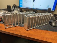
Hey guys I'm fairly new here and I don't post much at all but love reading the various topics on the forum. I have in my possession these beefy Jeff Rowland knockoff heat sinks and I was curious if these would be of adequate size to cool a First Watt F4 or F6 at an average bias level? I'm really interested in another amp project and would love to build one or both of these at some point in the near future.
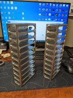
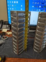
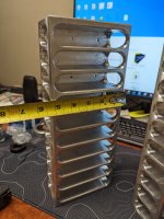
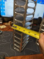
These heat sinks measure 13" Long X 5-1/4" Tall X 2-5/8" Deep. I know that I would need to sort out transistor mounting but that isn't an issue for me at all.
Thanks in advance for your time and advise guys!
These heat sinks measure 13" Long X 5-1/4" Tall X 2-5/8" Deep. I know that I would need to sort out transistor mounting but that isn't an issue for me at all.
Thanks in advance for your time and advise guys!
Attachments

Those are nice heatsinks! I would guess that they would dissipate quite a bit of heat; maybe 100 watts. When in doubt about the cooling capacity of a heatsink, I clamp some power resistor(s) to the heatsink and connect it up to a power supply to test it. Use Ohm's Law to figure out the current and calculate the power.
Probably would have to turn the bias down significantly to keep the device and sink temperatures within reason.
Those are nice heatsinks! I would guess that they would dissipate quite a bit of heat; maybe 100 watts. When in doubt about the cooling capacity of a heatsink, I clamp some power resistor(s) to the heatsink and connect it up to a power supply to test it. Use Ohm's Law to figure out the current and calculate the power.
Thanks, I'll have to see what I've got at work for test equipment, I should be able to sort something out
robably would have to turn the bias down significantly to keep the device and sink temperatures within reason
That's definitely a possibility, if it ends up that these won't work I'll just purchase the recommended heat sinks from the DIY Audio store and save these for another project. We'll see if I can test the power dissipation and go from there.
Quick way is to bolt a 100W chassis mount resistor where the transistors would be mounted, using thermal grease,
and orient the sink how it would be mounted. Crank it up to 100W with a lab power supply.
Measure the surface temperature at several places on the sink. If under 60C, probably ok.
If not, lower the supply until the temp is no more than 60C. Then calculate the dissipation with V^2/R.
That's how the bias would have to be set on the amplifier.
https://www.digikey.com/en/products/detail/ohmite-manufacturing-company/HS100%2010R%20F/16838160
That I doubt. The heat sinks do look nice but they don't have that much surface area. I would try to model them in this heat sink calculator: https://heatscapecal.com/naturalI would guess that they would dissipate quite a bit of heat; maybe 100 watts.
Obviously the model won't be perfect due to the limitations of the calculator, but it should get you close.
Tom
I didn't know this was a thing, I guess I shouldn't really be surprised. Thanks for this, it will be a great starting point since I currently do not have the required test equipment or parts.I would try to model them in this heat sink calculator: https://heatscapecal.com/natural
Obviously the model won't be perfect due to the limitations of the calculator, but it should get you close
MY F6 generates Less heat than the I5 cpu in My "puter.
Rarely exceeding 40 C.
Try and See ?? You can always add More when/if necessary
That said... those things look more like CNC 'offcuts' than Heatsinks.
Rarely exceeding 40 C.
Try and See ?? You can always add More when/if necessary
That said... those things look more like CNC 'offcuts' than Heatsinks.
On second look, I agree. Not many "fins".That I doubt. The heat sinks do look nice but they don't have that much surface area. I would try to model them in this heat sink calculator: https://heatscapecal.com/natural
Obviously the model won't be perfect due to the limitations of the calculator, but it should get you close.
Tom
I have a very rough figure of 75,000 K/W.mm^2. Calculate the surface area (count each side of a fin) and divide the 75,000 by the area in square mm. That is only applied to the fins, not the base plate.
That would represent the total capability (approx.) of the heatsink but does not include the resistance from e.g. the centre or where devices would be mounted. For that I would use the thermal conductivity of Al and dimensions. Probably, with what seems to be 6mm thick base plate another 0.2K/W.
Then I would also use a resistor with known heat input to check. 100W resistors are realtively cheap (or were) and could always buy a useful value like 8.2 ohms for dummy amplifier loads on another occasion. Need a thermocouple and DMM to measure, though. (or an old fashioned (mercury?) thermometer with thermal compound to make the interface. For a thermocouple I'd probably drill a small (approx 2mm) dia hole to mount it in somewhere about a quarter in from one end.
If you have access to a thermal camera ... ideal for measuring the dissipation along the heatsink, ( but you have to calibrate the surface emissivity of the heatsink which does not look like standard Al, some sort of polished finish ... which means known input power and temperature again!)
When I have some more time tomorrow I'll run through the heat sink calculation and see what I come up with. But it's sounding like these likely won't be a great fit for this project and for like $60 I can just buy the proper size heat sink from the DIY Audio store. I might end up going that route and use these for another project down the road since I really do like how they look.
- Home
- Amplifiers
- Solid State
- Heat sink question