You should consider adding a baffle step compensation on the woofer (inductor and resistor in parallel), you can modle the baffle step loss with a tool in VituixCAD. You should also raise the sharp impedance drops at 2.1 and 20kHz, as this will be too low for your amplifier to handle.

always a fun learning process
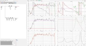
But the impedance curve is rather wild at the top end
huge dips and peaks.
Very high Q filters
This would be very unfriendly or all together damaging
to a amplifier.
Very close to 0 ohms then huge rise
try using the circuit blocks in the library.
to understand filter Q
But the impedance curve is rather wild at the top end
huge dips and peaks.
Very high Q filters
This would be very unfriendly or all together damaging
to a amplifier.
Very close to 0 ohms then huge rise
try using the circuit blocks in the library.
to understand filter Q
There are Many lowpass filters already present in the system, and noone would kill the very High frequency content of a given signal. 2 or 3 resistors, or even One, might suffice for tearing down that extra SPLThe tweeter probably doesn't need the low pass elements. If
I'm not against the use of a low pass filter for a tweeter, however this one could be responsible for the low impedance near 20k. It appears to have a high Q section. It's also probably unnecessary to have a fourth order filter in this position.
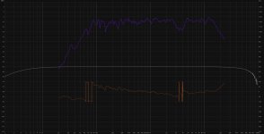
So here is what I came up with (for now), because I had those parts on hand 😀
Doesn't look to bad, definitly missing a lot of bass, didn't think the impact to be that big, but I am quite happy for now.
Doesn't look to bad, definitly missing a lot of bass, didn't think the impact to be that big, but I am quite happy for now.
Attachments
Did you measure ribbon with midwoofer in the circuit?
Otherwise you could benefit from a series RLC in parallel just before ribbon to get rid of the 5 kHz peak.
You should delay the tweeter with an appropriate HP filter of a higher order. Since mid is 3rd order, tweeter at least 4th.
Are drivers on a flat baffle, no tilting?

Otherwise you could benefit from a series RLC in parallel just before ribbon to get rid of the 5 kHz peak.
You should delay the tweeter with an appropriate HP filter of a higher order. Since mid is 3rd order, tweeter at least 4th.
Are drivers on a flat baffle, no tilting?
Sorry, your x-over doesn't make sense to me at all. For a small AMT much to low x-over frequency and a lot of unneccessary= counter productive parts. You have to build an x-over for the chassis, not for the left over parts you have. Sorry again, but polite ignoring doesn't help you at this point.
Start again for an x-over frequence of 3.5-4kHz.
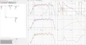
Another hint: Smooth your graphs a bit, all these spikes and drops distract from the aim and provoce useless corrections.
Start again for an x-over frequence of 3.5-4kHz.
Another hint: Smooth your graphs a bit, all these spikes and drops distract from the aim and provoce useless corrections.
Drivers are on a flat baffle, I did measure them completly seperate, but in the enclosure.
In fact I did aim for a 4kHz Crossover.
In fact I did aim for a 4kHz Crossover.
Yes, it shows that they have different delays so it appears as though you did that right.. but only you can be sure. Gating seems inadequate.
You probably need to give some attention to the AMT power handling capability, ie the minimum slope you use.. it may help to consider the advice of someone who uses the same/similar model.
You probably need to give some attention to the AMT power handling capability, ie the minimum slope you use.. it may help to consider the advice of someone who uses the same/similar model.
- Home
- Loudspeakers
- Multi-Way
- Rate my first Crossover please