Hello everyone,
I’m revisiting an old crossover design of mine which I consider a potential threat to my amplifier (or any amplifier for that matter). I hope some more experienced people with knowledge of electronics and how electrical networks work to help me better understand and define the impact of such design.
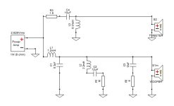
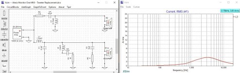
To cut the long story short, it’s all about the current going through the coil of the HP filter (see the first picture below). Due to relatively high value of the capacitor in series with the tweeter (10uF) as well as the small value of the coil in parallel (0.17 mH), it seems that the latter is effectively shunting huge amount of current to ground. At least, that’s my assumption and in order to establish exactly how much current I’m dealing with, I’ve ran a simulation using XSim (luckily I kept the ZMA files of the project). The XSim screenshot below (second picture) shows that the current through the coil reaches as high as 3.85 Amps at around 3 KHz when using 100W power / 8 ohms. This number alone doesn’t tell me much if not compared to some sort of a threshold. Here the Ohm's law comes in handy and according to my calculations a 100 watt amplifier on 8 ohms load is expected to deliver 3.53 Amps of current.
Obviously there’s an excessive amount of current going through that coil and all I want is to keep it at bay. I’am well aware of the possible solutions like lowering the cap value, increasing the inductance of the coil and so on. The small value of the resistor before the cap is not helping either. But attempting new crossover design is something I’d like to avoid for a number of reasons. That’s why I decided to mitigate the problem with a simple solution by using a resistor in parallel with the tweeter, which I soldered directly to its connectors. The value of 22 ohms seems reasonable for that purpose and now the current trough the coil is down to 3.52 Amps (see picture 3) which is exactly on the threshold. There’s a tradeoff as well - now the tweeter response is down with around 2 dB, but I don’t mind it. Actually, I think it’s even better that way.
Finally, I’ve measured the impedance of the speaker (picture 4) and you can see that its lowest point is around 3.8 Ohms at around 180 Hz which is also a reason for concern.
My question is whether the speakers with this final crossover pose a significant risk to an amplifier. Is the small adjustment with the resistor in parallel enough to effectively alleviate the problem and bring the current to more reasonable (not harmful) level.
I hope my calculations are correct and I’m not missing something along the way.
I’d very much appreciate your input 🙂
-Allex
I’m revisiting an old crossover design of mine which I consider a potential threat to my amplifier (or any amplifier for that matter). I hope some more experienced people with knowledge of electronics and how electrical networks work to help me better understand and define the impact of such design.
To cut the long story short, it’s all about the current going through the coil of the HP filter (see the first picture below). Due to relatively high value of the capacitor in series with the tweeter (10uF) as well as the small value of the coil in parallel (0.17 mH), it seems that the latter is effectively shunting huge amount of current to ground. At least, that’s my assumption and in order to establish exactly how much current I’m dealing with, I’ve ran a simulation using XSim (luckily I kept the ZMA files of the project). The XSim screenshot below (second picture) shows that the current through the coil reaches as high as 3.85 Amps at around 3 KHz when using 100W power / 8 ohms. This number alone doesn’t tell me much if not compared to some sort of a threshold. Here the Ohm's law comes in handy and according to my calculations a 100 watt amplifier on 8 ohms load is expected to deliver 3.53 Amps of current.
Obviously there’s an excessive amount of current going through that coil and all I want is to keep it at bay. I’am well aware of the possible solutions like lowering the cap value, increasing the inductance of the coil and so on. The small value of the resistor before the cap is not helping either. But attempting new crossover design is something I’d like to avoid for a number of reasons. That’s why I decided to mitigate the problem with a simple solution by using a resistor in parallel with the tweeter, which I soldered directly to its connectors. The value of 22 ohms seems reasonable for that purpose and now the current trough the coil is down to 3.52 Amps (see picture 3) which is exactly on the threshold. There’s a tradeoff as well - now the tweeter response is down with around 2 dB, but I don’t mind it. Actually, I think it’s even better that way.
Finally, I’ve measured the impedance of the speaker (picture 4) and you can see that its lowest point is around 3.8 Ohms at around 180 Hz which is also a reason for concern.
My question is whether the speakers with this final crossover pose a significant risk to an amplifier. Is the small adjustment with the resistor in parallel enough to effectively alleviate the problem and bring the current to more reasonable (not harmful) level.
I hope my calculations are correct and I’m not missing something along the way.
I’d very much appreciate your input 🙂
-Allex
Attachments


One thing that goes along with this development is that the high pass filter is high Q. Is that what you need here?
Did you ever measure the response of the speaker? Tweeter /woofer without x-over, tweeter/ woofer separate, but with x-over and complete response, one in phase and one reversed? I don't see any problems in your impedance curve. A normal 4 Ohm speaker, even as the part values of the x-over seem odd.
Well, this crossover dates back to a few years ago and I can’t remember what exactly I was trying to achieve, apart from a smooth and flat frequency response, of course. I’m not very experienced in crossover design, so I assume that the high Q is more like a result than a goal of itself. I do remember though, that I was experimenting quite a bit with different crossover points and various designs, leading to this one being the most satisfying in terms of sound and FR.One thing that goes along with this development is that the high pass filter is high Q. Is that what you need here?
It's easy to do when working by ear. You're right to look at the impedance here and it's OK as it is.
Yes, I measured with a microphone separately and with the crossover, but unfortunately I don’t have the FRD files anymore. A few days ago I measured the FR with the aforementioned resistor in parallel to the tweeter and I got this:Did you ever measure the response of the speaker? Tweeter /woofer without x-over, tweeter/ woofer separate, but with x-over and complete response, one in phase and one reversed? I don't see any problems in your impedance curve. A normal 4 Ohm speaker, even as the part values of the x-over seem odd.
I also remember that when I finished this crossover before I also measured with the tweeter inverted and a got a nice and deep dip in the area of the crossover frequency, so I took that as sign of a fairly reasonable crossover design in general.
Last edited:
I'm quite sure the x-over could be improved, but honestly not how, from the data supplied. It could be a good idea to start the x-over from scratch, as to me the values of the parts are a bit strange.
XSim is assuming 100W of input power going to tweeter branch which is not a realistic scenario. You have to instruct the program the actual input power and then evaluate power ratings. Should you really feed tweeter with such of an input signal, the inductor would be the least of your problems. You think tweeter would have survived it?

I agree with all thoughts here. Looks good in performance and measurements. I do not see a high current fire hazard here.
OK, thank you all for your thoughts 🙂
I’m quite happy with the performance of the speakers with this crossover, so I just wanted to make sure it’s safe. My concern is based on an observation that my amplifier is sometimes getting warmer when using it with these speakers compared to the other ones that I have, which are 8 Ohms. For a long time I was thinking that the reason for this is simply the lower impedance, but wanted to make sure I didn’t do anything stupid when developing the crossover. Hence my attempt to check it again and see if there’s something which draws more current than what the amp is expected to deliver, and thus, causing more heat.
As for the more realistic scenario suggested by Lojzek about the input power in XSim, I agree with what has been stated in general, but this is the actual power rating of my amplifier and that’s why I’ve set it like this in Xsim. I just thought that’s the right thing to do when evaluating the current trough shunts in my crossover network.
Even if I change the output power of the amp in XSim, the things seem to be the same - yes the numbers are different, but the principle remains unchanged. Here is an example:
I’ve set up the amp in XSim to the more realistic 10W / 8Ohm. Now the current trough the coil is 1.23 Amps. A 10 Watt amplifier on 8 Ohms delivers about 8.94 Volts resulting in 1.11 Amps of current. As we can see the current trough the coil is once again exceeding this figure. When introducing the 22 Ohms resistor in parallel to the tweeter the resulting current trough the coil gets drawn to 1.11 Amps, which is basically the same result as the one I got before.
I’ve already explained I’m not an engineer, so I realise my approach might not be very accurate and that’s why I turned to the DIY community here for help. Once again, thank you all for your time.
- Home
- Loudspeakers
- Multi-Way
- Safety concerns about a particular crossover design