Maybe post your complete crossover? Impedance peaks can be a big problem to deal with in a crossover.
To me, that looks like ripples caused by the horn and I have seen it as well. Doesn’t show up on all horns however. Curious to hear what other more experienced members have to say about this.
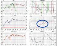
Which parts of the response do find to be the most problematic? Also is the dip between 300hz and 450 hz a room mode or something that exists die to the driver or enclosure?
comp driver filter responseWhich parts of the response do find to be the most problematic? Also is the dip between 300hz and 450 hz a room mode or something that exists die to the driver or enclosure?
Something like this might get you closer as far as avoiding the impedance peaks. You would need a 20 mH tapped inductor though. I just like to avoid large L pads on a compression driver also.
You get 6 DB attenuation from the tapped inductor and should have about 4 DB shelving with the 6 microfarad and 8 ohm reistor.

You get 6 DB attenuation from the tapped inductor and should have about 4 DB shelving with the 6 microfarad and 8 ohm reistor.
Where to find taped inductor? I've asked toroidal manufacturer and he made big eyes what I'm asking for.
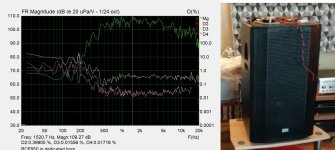
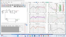
The impedance bumps will do some funky things to your filter function, for sure. For example here is a real 2" driver on a horn (blue) as compared to a purely resistive load (gray.) Because of the impedance peaks and curves, you don't get the perfect Linkwitz-Riley 2nd order high pass at 700 Hz.

But what happens if a swamping resistor or an L-Pad is used? Below is the same driver with a 6dB L-Pad in front of it. We are already at a better match for the filter function wanted.

L-Pads are normally use for a horn in a passive system, I have also used them in active systems, for impedance and noise issues.
But they aren't perfect, sometimes they can tilt up the FR. Although that is often a good thing for horns. I have typical used and attenuation circa 10dB on the horn.
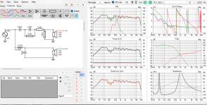
This is why measuring impedance and using simulation software can save so much time. Try before you build that crossover. To get the acoustic target you want, you'll need to try different R,C,L values in your crossover.
NOTE: What is shown above is just the filter function, not the acoustic response of the driver+horn.
But what happens if a swamping resistor or an L-Pad is used? Below is the same driver with a 6dB L-Pad in front of it. We are already at a better match for the filter function wanted.
L-Pads are normally use for a horn in a passive system, I have also used them in active systems, for impedance and noise issues.
But they aren't perfect, sometimes they can tilt up the FR. Although that is often a good thing for horns. I have typical used and attenuation circa 10dB on the horn.
This is why measuring impedance and using simulation software can save so much time. Try before you build that crossover. To get the acoustic target you want, you'll need to try different R,C,L values in your crossover.
NOTE: What is shown above is just the filter function, not the acoustic response of the driver+horn.
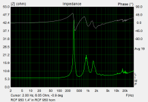
RCF950 horn is slot type with fins - this explains worse impedance response. Second order filter helps. Now did you try fill ceiling dip with smaller speaker? 15 inch woofer is close to floor. Or use small woofer arary with horn?
Attachments
For simple 1st order high pass with capacitor you could use use parallel inductor instead. You can do this when there is also a pad to prevent short circuit for the amplifier on low frequencies.


It might not work if its high power application, full bandwidth goes the resistor which means serious heat.
If this trick don't help use series notch in parallel with the driver, this will EQ the peaks.

It might not work if its high power application, full bandwidth goes the resistor which means serious heat.
If this trick don't help use series notch in parallel with the driver, this will EQ the peaks.
This is not a tapped inductance it is a transformer.Can we simulate tapped inductor in Vituix?
For simple 1st order high pass with capacitor you could use use parallel inductor instead. You can do this when there is also a pad to prevent short circuit for the amplifier on low frequencies.
Inductor after the Lpad require high value capacitor before.
Parts are omitted and shorted in the schema so perhaps the images were confusing. There is no L-pad with the parallel inductor, just series resistor making the pad. I think there is no need for cap, unless high power app. Of course you can use capacitor as well, makes it second order filter.
edit. spent minute to clean up to avoid confusion.


edit. spent minute to clean up to avoid confusion.
Last edited:

If you mean that they don't go away - why would they? A series resistor will just scale up everything.that don't go with series resistor.
The nature of the resonances caused by compression driver impedance peaks means you are normally better using Zobel compensation. This often means at least multiple series RLC circuits across the driver and maybe some parallel resistance for good measure.
Doing things in series instead will tend to mean it's difficult to change things when the time comes, as well as difficult to design in the first place.
I also don't think a transformer is the answer, as the peaks will be the same in a relative sense.
Doing things in series instead will tend to mean it's difficult to change things when the time comes, as well as difficult to design in the first place.
I also don't think a transformer is the answer, as the peaks will be the same in a relative sense.
- Home
- Loudspeakers
- Multi-Way
- 2" compression drivers problem with impedance peaks